Time to read: 6 min
Any professional mechanical engineer knows that Finite Element Analysis (FEA) is an essential tool used to analyze stress (deflection, FOS, and more) in a design based on different loading conditions. A huge part of conducting FEA centers around research. When you start the process, you don’t yet know what you don’t know. You need to begin the process in order to validate or reformulate your assumptions, and ultimately justify your decisions, as all well-trained engineers should.
In this post, I’m going to walk you step-by-step through the process I used to validate designs for Fictiv’s face shield project, using a simple FEA inside Solidworks.
This includes using Hooke’s law, which applies to the linear portion of a material stress strain curve. Materials have an elastic region, and the slope of these regions is the modulus of elasticity, or Young’s modulus. Using this linear relationship allows the application of Hooke’s law to be used on a FEA analysis. Utilization of this method can save you time and help you narrow in your analysis quickly, while (seemingly) not knowing enough information.
How to Conduct a Finite Element Analysis (FEA): Where to Start
I already had my design in Solidworks, so I was able to hop right over into simulation. Apply the material; apply some boundary conditions; and solve. Well, immediately you might be like, “Whoa, whoa, whoa, when it comes to FEA, garbage in equals garbage out.” Yes, but it’s really important to do a little homework, engineer things, and figure them out for yourself.
For a Finite Element Analysis, you need:
- A model
- A material
- Boundary conditions
- A Mesh that doesn’t fail
For simple single parts, start with a table, like Table 1 below, to capture what you’re doing.
Table 1: Parts required for FEA analysis

Include part number and revision, if you have them.
Also, write down why: What’s the purpose of what you’re doing? When you start, keep it simple. You’re on a learning path. You’ll likely learn much more and become a super nerd about your specific problem along the way.
The bolded text is what I started with (my purpose), and then I added the rest (as I learned):
The purpose of this study is to analyze the strength of the face shield head band. The analysis will determine the maximum stress caused by the head size of either a 5th percentile woman (smallest size) or 95th percentile male (largest size) and will determine the output factor of safety and max stress predicted from their conditions. Additionally, we will determine the total force required by the head strap band to keep the mask affixed to a user’s face.
Take notes and write a report, documenting your work—it doesn’t take that long and can be used much further down the road, when you need to look back and see what you were thinking then (or your boss goes, “What have you been doing?”).
Next, I add my material, which you can do in Solidworks, by changing the parameters in Solidworks fairly easily. If you don’t know how, there are many aspiring YouTubers who will help you. Do I have my CAD model? Check. Have I applied my material? Check.
Boundary Conditions Make or Break Your FEA (pun intended)
Next, I established boundary conditions. I went to Google and searched for anthropometric data on the 95% male head. Did I know it was 95% when I started this search? No, I did not. But when your first search result is from NASA, and they stop at the 95% male head dimensions, you know you need-not keep searching. (Rule number 28 of random (wedding crashing) engineering tidbits: NASA is a good benchmark.) In general, if you can find credible sources like scholarly articles or mil-specs, you can generally assume that information is correct and suspend your quest for further clarification.
I now had my first equation/problem to solve: How much was this 95% male head going to stretch out the proposed design?
Thought process:
Width of my head band – width of the head = a negative number of how much said band needs to stretch!
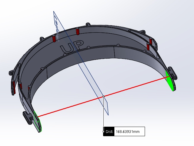
Bzzz: I was wrong. I did the calculation and got a clearance (see below):
This means that for the 95th percentile male head, the total expansion/contraction would need to be:
Scenario 1: Total Clearance=168.6-165=3.3 mm
I immediately thought, well, shoot, if it’s wide enough for this, and it needs to contract, then for a small female head, it’s going to need to contract way more! Back to the calc and back to NASA tables. Also, back to the top of my study, to expand the scope.
Following the same guidelines, I added my second scenario:
For the 5th percentile female head, the total head width is 144 mm.
Scenario 2: Total Clearance=168.6-144=12.3 mm
OK, so this part was right. The design would have to contract more. Now that I had a total clearance, I decided to assume that each side flexes equally and that people’s heads are mainly symmetrical. I took my total clearances and divided them by 2, to know how far each side of the head band would need to flex.
(If you’ve made it this far, this is really where I’m going to show you some tricks to get you where you need to go faster.)
To fully set up my boundary conditions, I divided my model in half and assumed it was symmetrical (that’s why I divided by 2 up above). I then fixed the portion of my cut in the FEA analysis (see green arrows). I then added a 1 N load to the head band strap fixation area (see image below).
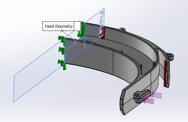
In rough, I had my simple boundary conditions of a more fancy looking cantilever beam scenario. Since I didn’t actually know my load force, I knew my target deflection. And since I have the simple, cheap FEA on Solidworks, I ran my analysis with a simple 1N load. And I got my results:
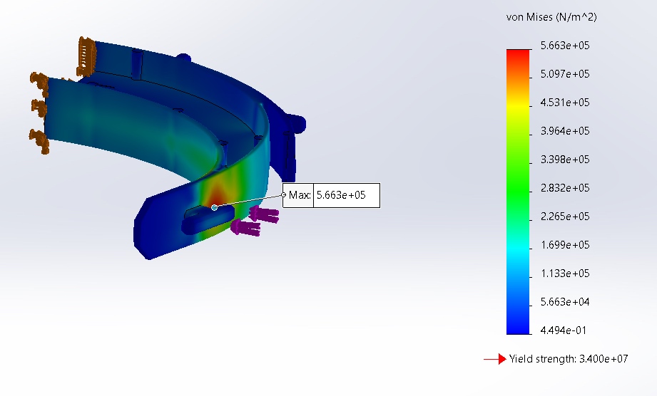
For Taipro PP K1011, the maximum reported stress of Face B, and at a unit load of 1 N, was 5.633*10^5 Pa.
The deflection for the same 1 N unit load was 0.1695 mm.

Why did I just spend the time to get the deflection and the stress? When you use these two results with the unit load, you can get a ratio of stress to displacement.
Using Hooke’s Law for FEA
Using Hooke’s law, we know that the stress is considered linear, as long as the material property has not yielded (meaning you have to check this assumption). So now, I could use the two values I quickly got in Solidworks FEA and calculate my way to results with basic math to the force/stress required to fully squeeze in my head band! (P.S. You are now actually engineering your way to success–be proud of yourself!)

Using the displacement from a unit load of 1 N and solving for the stress caused by a displacement of 6.15 mm. Solving for the equivalent stress:
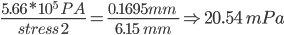
Evaluating that against the yield of my selected material, this is less than the 34 mPa yield strength of the material. This condition is not expected to yield the product.
The required force to obtain this deflection is estimated to be:

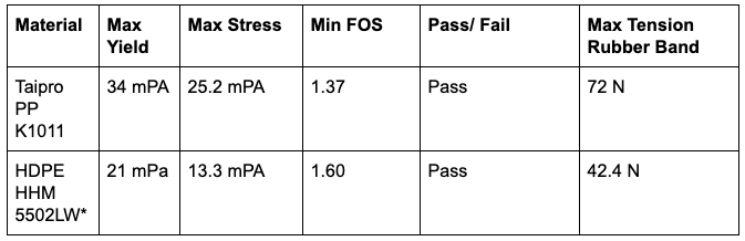
Using these values, we reran the simulation, and the max stress was 25.2 mPa, with a resulting factor of safety of 1.37 for the 5th percentile women. (Note: These stresses can differ from your calc and may be caused by modeling items. This is to help you get to end conditions faster, as before, you’d be guessing what the load would be to cause deflection).
Following the same method, I was able to determine the max load needed for the strap, that the stress at the big head and little head extremes would not break the head band. And I didn’t trap myself into running a zillion iterations on my FEA analysis.
Table 2: Summary of results
That’s it (for this issue). The last thing I did was check for the strain energy and write it all up nice and neat. Then I got a good night’s sleep, knowing my design would do what it needed to do, because I engineered my way there.