Time to read: 4 min
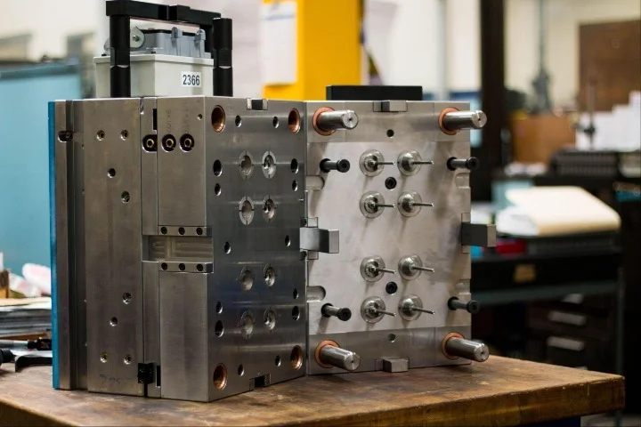
Developing a robotic joint may seem like an overwhelming task, but there are some common issues that can be tackled ahead of time to make your project easier to manage. There are a lot of parts to stuff into a small space – typically, a joint has motors, transmission, encoders, brakes, electronics, and wiring. One of the most common tasks is managing the fit up of bearings and transmissions to a housing. This article provides a guide on mechanical assembly and machined parts with precision fits.
Capabilities vs. Specifications
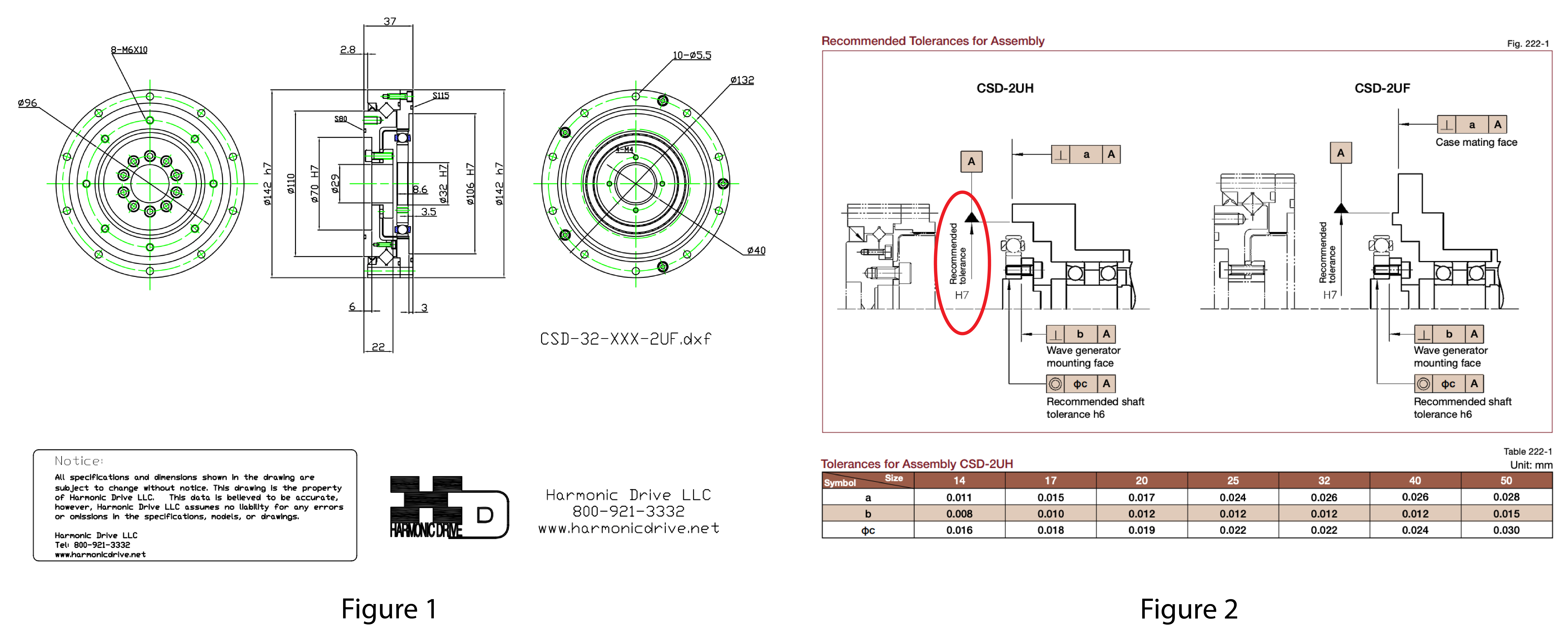
Most every robot joint houses a transmission, commonly a harmonic or strain wave gear set. The manufacturer will give the designer a specification for the fit of the gear set to the housing. Many components will be specified in the ISO fit system. For example, in Figure 1, a gear set is specified as an h7 fit for the internal diameter. In Figure 2, the outer diameter is specified as an H7 fit. So the goal for fit between the housing and the gear set is a 142mm h7/H7 fit – what does this mean?
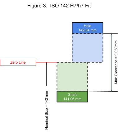
Figure 3 shows the layout of the ISO fit the manufacture is specifying for the gear set. What this means is that the gear set will be manufactured 142mm 0.00/-0.04, and the housing the gearset fits into will should ideally be manufactured to 142mm 0.04/0.00.
What about the machine shop? Can it make the part to the tolerance the manufacturer specified? Let’s say the CNC machine shop can hold a tolerance of +/- 0.025mm. This would mean they would be able to produce a part a little out of tolerance to the H7 fit by about 5 microns per side. For some perspective, spider silk is 3-8 microns!
Without going to the formalism of calculating a Cpk, think of the shop’s capability as a normal curve. If the housing were machined from the middle of the range, the resulting part would range from 141.995 to 142.045mm. The distribution of the tolerances would look like Figure 4. The figure assumes that the +/- 0.025mm corresponds to +/- 3.
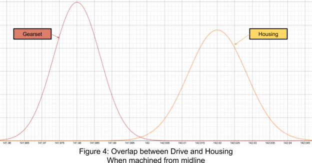
The takeaway here is that there is a very good chance that a shop capable of offering +/- 0.025mm will deliver housings that meet the specified H7 callout with minimal fallout.
Communication is Key
So far it sounds like making a robot joint is easy! Basically, read the manufacturer’s catalog, find a good machine shop and you’re good to go! So where can things go wrong?
Using ISO standard fits can create a mismatch between the machined part 3D file and the component to be installed. For example, if the surface the gearset is modeled at the “nominal size” shown in Figure 3. This creates possibility the part would be made to 142mm 0.025/-0.025. This is particularly true if the 3D file is modeled with the housing surface at a diameter of 142mm which is the “zero line” in Figure 3 and the shop uses the 3D file to program the tool paths. This scenario is outlined in Figure 5.
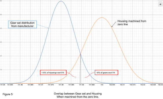
Looking at Figure 5 a few items are worth noting:
- ½ of the housings are out of tolerance since they are below the minimum 142.000mm of the H7 fit. This would result in the lot being rejected.
- If the lot were 100% inspected and matched assemblies were created to bin the two distributions together, about 10% of housings would be scrapped.
Drawing Callouts and 3D files
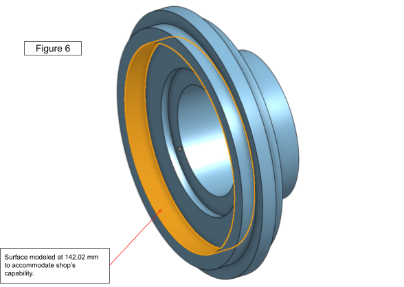
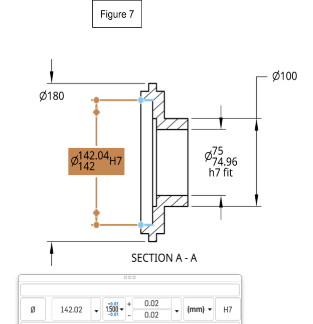
One way for avoiding this situation is to model the 3D file with a small offset to put the machined surface in the middle of the shop’s tolerance (see Figure 6). This way the machine shop can use CAM software directly on the 3D model and centers the surface to the shop’s published capability. Keeping the ISO standard on the drawing keeps the ISO standard information and helps preserve design intent relative to the manufacturer’s recommendation (see Figure 7).
Putting It All Together
Once you receive your parts, don’t be in a rush to put them together. This kind of high aspect ratio fit requires very specific alignment or experienced assemblers to make sure the part does bind during installation. When doing these types of fits it is recommended to add extras to your order to accommodate fixture development or fallout during assembly.
Best Practices
Using a rapid manufacturing approach for higher tolerances parts works well in robotics and can markedly speed up a design program. A few simple tips will help you be successful:
- Keep 2D and 3D data in sync, consider using auxiliary features in the 3D model to support bilateral tolerances.
- Be mindful of the normal distribution of tolerances even if expressing your design intent using the ISO unilateral fit system.
- Follow manufacturers recommended fits.
- Consider adding first article inspection, even on small quantities, to gain insight on where tolerances can be relaxed while still supporting design intent.
- Add a few extra parts to aid during the assembly process.