Time to read: 5 min
Tolerances — the amount of acceptable variation from a design for a part to still function — are an integral part of any engineering design process. There are many books, courses, training seminars, companies, and even professions devoted to tolerances/geometric dimensioning and tolerancing (GD&T). Tolerances help us, as engineers, ensure our products are manufactured so that they fit into the assemblies they belong to.
Ensuring you can correctly determine, assign and convey tolerances is critical for CNC machined part drawing preparation. This article explains what CNC machining tolerances are, how they’re determined, the different types of CNC tolerances, and our best tips for CNC machining tolerances.

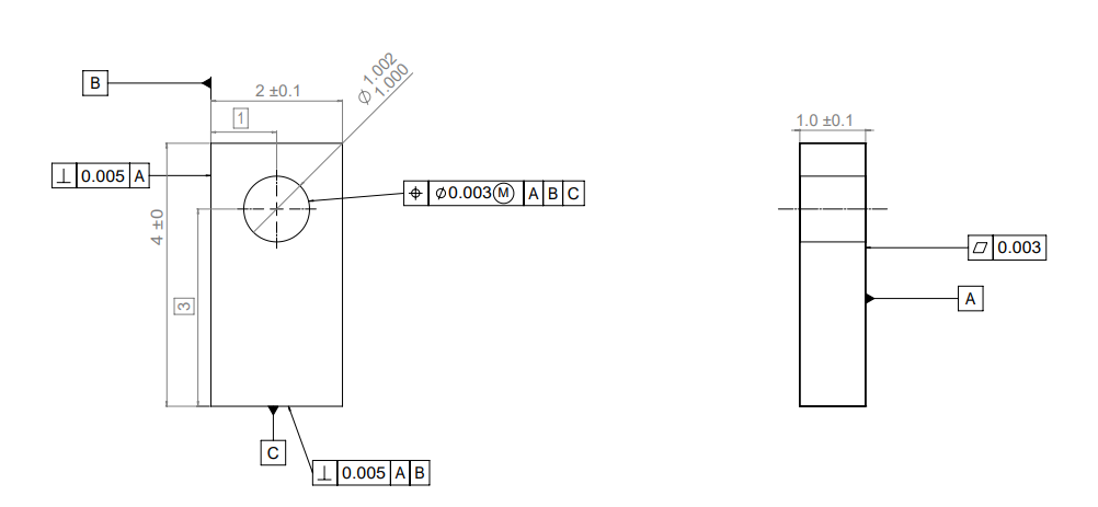
Pro-Tip: For more check out our GD&T Visual Guide to see how tolerances are applied.
What is a CNC Machining Tolerance?
As previously mentioned, tolerances are the amount of acceptable variation that a certain dimension can have that still allows proper fit and function of the part. ASME defines engineering tolerance as the total amount that a specific dimension is allowed to vary from the basic value of the dimension.
Tolerances are measured as part of post-CNC machining quality inspection. Required tolerances also help to determine the manufacturing methods necessary to machine a certain part. Tighter tolerances may require more sophisticated manufacturing equipment or additional post-processing to get the dimensions within the specified ranges.
Where do CNC Machining Tolerances Come from?
We all know that CNC-machined parts are not perfect. We can expect to see variations among machined parts. These unavoidable variations can be attributed to many factors:
- Raw material type: You can hold tighter tolerances with harder materials. This is because the materials tend to hold their shape and deflect less during machining. Therefore, harder materials have more dimensional stability than softer materials. Also, materials not as readily impacted by temperature fluctuations — those with a lower coefficient of thermal expansion (CTE) — can allow for tighter tolerances.
- Raw material condition: Starting out with stock material that is homogenous and true to size and shape goes a long way in reducing variations. The quality of your raw materials impacts the quality of your finished product.
- CNC machine used to manufacture the parts: While it’s not always true that more expensive machinery results in higher quality parts, it usually works that way. Machines that can hold tighter tolerances are often made with higher quality, truer raw materials, and have more sophisticated programming to ensure precise tooling positioning with respect to the part being milled.
- Tooling: if your tooling isn’t precise and accurate, you won’t get tight tolerances, no matter what work you do to prepare your material.
Regardless of the origin of the tolerance (and it’s nearly impossible to determine the origin), ensuring you have a correct understanding of the places where tolerances can stack during CNC machining is essential to correctly define your tolerances.
Types of CNC Machining Tolerances
Within the possible allowable variation for CNC machined parts, there are several types of tolerances that may be defined and utilized, including:
Standard Tolerances
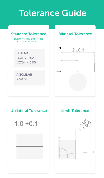
Standard tolerances are among the most commonly utilized methods for defining the variation of a CNC machined part’s dimensions. Standard tolerances may be what a machine shop is capable of producing without additional cost. Or, they may be a blanket variation applied to an entire drawing as defined in a note or in the title block — unless otherwise noted in the drawing or on specific features. Standard tolerances may also refer to tolerances applied per an industry standard, such as:
Bilateral Tolerances
Bilateral means having or relating to two sides or affecting both sides. Bilateral tolerances apply to both the plus and minus tolerance limits on a specific dimension or condition, so they give the minimum size and maximum size tolerance for a specific dimension. A bilateral tolerance may be the same for the plus and minus tolerance, or it may be different for one of them.
Unilateral Tolerances
Unilateral means having or relating to one side. Unilateral tolerances are only applied to one direction: a plus or minus tolerance. For GD&T, the unilateral tolerance is known as the unequally disposed tolerance and is prefixed with a U symbol. Most often, a unilateral tolerance should be applied at maximum material condition (MMC). Check out GD&T 101: An Introduction to Geometric Dimensioning and Tolerancing for more information on MMC.
Limit Tolerances
A limit tolerance is simply a listed min and max dimension allowance on a drawing. These may also be known as limits of size because the upper limit and lower limit for the size of a feature is provided on a drawing. This allows for quick and easy determination of whether a measured dimension is within the tolerance zone for a feature or dimension, without having to calculate the boundary dimensions from tolerance values.
GD&T
GD&T, or Geometric Dimensioning & Tolerancing is the process of applying tolerances and dimensions based on the geometry of your part. GD&T works off a datum reference frame, feature control frames, and tolerance symbols to fully define a part.
GD&T vs coordinate dimensioning, or true positioning vs coordinate dimensions, is a decision that companies must make to either provide better quality or contend with modern requirements. GD&T provides several advantages over a coordinate tolerancing system such as: clear measurement requirements, a focus on function (as opposed to just fit), a larger allowable tolerance area (circular position tolerance vs a square tolerance zone), and bonus tolerance.
Below is a summary table of the various types of tolerances you will see on a CNC machining drawing:

More Tolerance and GD&T Resources
Now that you’re up to speed on all things related to CNC machining tolerances, check out these other resources that can help you learn more about using CNC tolerances to improve your designs:
- Conveying Design Intent with GD&T
- GD&T: A Step-By-Step Guide
- GD&T 101: An Introduction to Geometric Dimensioning and Tolerancing
- Conveying Design Intent with GD&T
- The Complete Guide to Designing Tight Tolerance Parts
- What is ISO 2768? A Guide to Tolerance Standards for CNC Machining
Sourcing Simplified – Start Your Next Project With Fictiv
For all your CNC machining and finishing needs, Fictiv’s CNC machining service has you covered. We’re experts at producing custom CNC-machined, tight-tolerance parts in a variety of materials. And, we simplify custom part sourcing with intelligent, streamlined, automated workflows. Fictiv is your operating system for custom manufacturing that makes part procurement faster, easier, and more efficient.
And if you need assistance with your tolerancing process, create an account, upload your design and reach out to one of our experts. We’re here to help, so find out what our instant quote process, design for manufacturability feedback, and intelligent platform can do for you.


