Time to read: 9 min
The computer modeling world is a vast array of techniques and programs that can serve as tools in aiding professionals to create, simulate, and visualize their designs. This article will introduce some different types of 3D modeling software and then walk through a sample workflow in Solidworks to show you what you can do with this software.
3D Computer Modeling Programs
Depending on your industry, you might be using at least one of these popular computer program categories:
- CAD/CAE (Computer Aided Design/Engineering): typically used in mechanical, automotive, aerospace and other engineering fields. Some examples: Solidworks, Autodesk Inventor, Autocad, PTC Creo (Pro/Engineering), Catia.

- NURBS (Non-uniform rational basis spline): used to create technical surfaces such as Class-A in automotive and industrial design. Example: Alias

- Polygonal Modeling: mostly for media, film and video games, but in the last few years it has been used to create complex and accurate representations for engineering, robotics, theme industry and medical animation too. Examples: 3ds Max, Maya

- Digital Sculpting: originally intended for media, film and video games. Due to its capabilities for high-detail, it has been also used for toy design, manufacturing, 3D printing, theme industry, architecture, and medical animation, among others. Examples: Zbrush, Mudbox


CAD/CAE Skills Improvement
If you have taken a CAD training course or watched tutorials, you probably started by creating a new file, learned how to use the mouse, selected one of the planes “Front” “Right” or “Top”, and then sketched a 2D profile on one of those planes. What is the next thing you do? Without hesitating, you click the magic button “Extrude” so the 2D profile results in a 3D Solid, accompanied by excitement (sound familiar?).
Don’t get me wrong, the first 3D solid model you create makes you feel as if you had been on a desert island and you just started a fire with a couple of rocks. The problem is that most CAD training courses and tutorials start by teaching you almost like a baking recipe. I don’t bake, but my wife and I have been watching the “Great British Baking Show”, highly recommended. If we get used to tutorials recipe steps, then we get lost when we don’t have all the information they used. If you watch the baking show, you know what I mean when the contestants are asked to bake a particular item without knowing the temperature of the oven or time it takes to bake.
One common “recipe” is to rely on the default sketching plane names that come with the software typically named “Front”, “Top” and “Right”. This can cause misunderstandings, especially during exporting/importing between software. Take for example Solidworks and AutoCAD, shown in Figure 6. By default, the plane “XY” is “Front” in Solidworks, but in AutoCAD it is actually “Top”. So when you transfer geometry between the software, you might end up with rotated geometry. To avoid this issue, always keep an eye on “X”, “Y”, “Z”, and if possible, change the names of the planes to “XY”, “XZ” and “YZ”. If you are still having issues when importing/exporting, try a basic geometry first, like a cylinder or a 3D arrow, it will help you to visualize and understand the direction of the geometry when imported to the second program.

Fundamental 3D Modeling Concepts
Product development is often organized functionally around sections of the product, sometimes called assemblies or systems. For example, in a car, you have suspension, powertrain, body, chassis and others as systems. Engineers are assigned a part or group of parts and are then responsible for completing the design. In CAD/CAE, it is critical that you not only understand the limits of the system you are working on, but how your work interacts with the rest of the whole product. You might be asked to reduce the mass of your design, but by shifting the center of gravity your parts might affect the loads in other areas not included in your design. If you don’t document and communicate the changes, the other teams might be working with obsolete revisions. Another typical error can happen when geometry is modified, resulting in interferences or clashing of parts.
The good news is that CAD/CAE software keeps evolving, by adding new features and tools to facilitate our lives. Checking for interferences and tracking revisions are common tasks, but it doesn’t end there. Different engineering calculations can be performed parametrically validating iterations during design phase.
For instance: applying materials to your geometry allows you to not only measure mass, but also calculate moments of inertia which are useful when selecting a motor or for other calculations. Figure 7 shows a quick example that compares hand calculation with CAD/CAE evaluation: the outside radius of the ring is 75mm, inside radius 55mm, thickness 10mm and it is made of A36 Steel (density 7.85×10⁻⁶ kg/mm3). Since we know the dimensions of the ring, we can calculate the volume (V) and then mass (m) since we also know the material density (d). Then with mass and the radius, we can calculate the moment of inertia. For hand calculations we get approximately 0.64 kg and 2773190 kg mm2, which are close to the estimate provided by a CAD software like Solidworks (m= 641.2 grams; Pz= 2773184.35 kg mm2).


Sample 3D Modeling Workflow
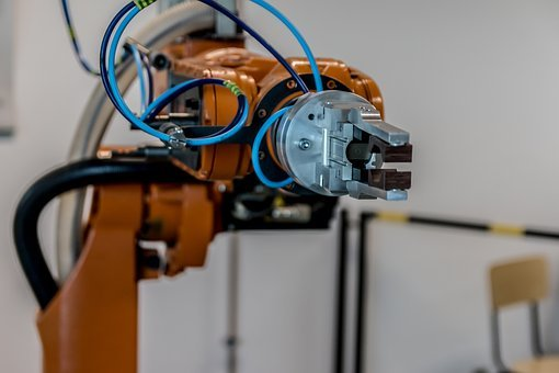
To elaborate, we will show you one of the multiple ways CAD/CAE is utilized for creating designs. We will use a hypothetical scenario: let’s say you are working for a manufacturing company and you are about to install an industrial robot like the ones shown on Figure 3. You realize you cannot anchor the robot to the floor because you need the robot to reach a higher position. After defining the project requirements, you start creating geometry such as the parametric sketch shown on Figure 8, representing the base plate where the robot will be bolted; and the centerlines of the columns that will be anchored to the ground serving as structure to raise the assembly. You can include the bolts location and the contact surface between the robot and your plate. Notice we are defining our work volume, but we are also considering what happens with the interacting elements, in this case the robot bolts.

The next step is to create the 3D solid of the base plate (Figure 9). One useful trick is to split the top surface or face of the plate by projecting the bolts and robot contact area. We will need this to analyze our design using a numerical technique, called Finite Element Method. This is when we are interested in the contact stresses between our plate and the bolts, or when we are checking if we are using the appropriate bolt sizes.

Next step: columns. In addition to parts and assemblies, most CAD/CAE software allow you to create multiple solids in the same part file. Those multiple solids can be split to an assembly later. This technique brings your designs to completion faster and easier to control.
But before creating the 3D columns, you need to create the 2D cross section which will be extruded forming the 3D of the column. Our framework example is simple with only four columns, so extruding for each one or creating a copy pattern is not that difficult. In other real life applications, you might end with more and more complex centerlines. For that reason, most CAD/CAE programs already offer a tool that includes a library of weldment profiles based on engineering standards and an automatic way to create the 3D; just by selecting the profile and the centerline. You can also customize your own 2D profiles and add them to the library.


The beauty of the weldment libraries tool is that you can create several design iterations in a short time, for examples see Figures 11, 12 and 13.


If necessary, you can add new sketch lines and new weldment elements for diagonal supports. When this is done, you might consider trimming or mitering the connection between members. CAD/CAE programs include automatic tools to develop those connections as shown in Figure 14 and 15, so you don’t have to manually model the compound cut surfaces.


Now that we have our geometry, it is time to do a first pass calculation to find out if our design is heading in the right direction. Most CAD/CAE programs include FEM modules (Finite Element Method) and despite that they don’t have the same capabilities of the more specialized FEM programs such as Ansys, Comsol, Nastran; we can still create different types of stress analysis simulations.
Welding sizes can be estimated either for American or European Welding Standard, as shown in Figures 16 and 17, using Electrode material properties and design codes factors.


As mentioned before, we can perform stress analysis, either static or dynamic. To calculate stress either normal, shear or principals; you need the forces. See the next equation, where “F” is the Vector of node forces and moments, “K”, Element stiffness matrix and “x,” Vector of node displacements. Hand calculating these matrices and vectors for a simple geometry would not be challenging, but when the geometry is complex, or when nonlinearities and multiple physics interact with our design, a computer numerical technique like FEM proves to be useful.

For our example, if you know the motion of the robot, you can estimate the accelerations and then forces and moments that will be applied to the base plate. The stresses can be visualized and compared with material properties. Resulting forces on the nodes adjacent to welding chords or the bolts can be extracted for post-processing and calculation. Our fictional example only shows you steps, so I omitted the legend with stress results for the next figures. When you create this type of analysis, you have the advantage of displaying the range of values and assigning a color legend where maximum and minimum can be identified to compare with material properties or design criteria.
In reality, there are different ways to simulate welding and bolts. Some of them include modeling the contact area as split surfaces, others actually model a simplified bolt and welding chord geometry; you can choose what to use depending on what you are looking for and how much time you have to finish your design. You will also need to refine the mesh on important zones for example on the contact areas.


Finally, we can assemble our framework with our robot to create shop drawings, checking for bolt alignment or even creating a cool product presentation.

In summary, this article showed one of the multiple different workflows and types of 3D modeling software. As demonstrated above, one of the advantages of the 3D modeling software is the quick generation of designs with physics, mechanical analysis and manufacturing constraints that can be evaluated on your design before ramping up production, so failures and risks can be detected at early stages of design. It is important for you to always validate your design and not blindly trust computer results. Remember, the acronym is CAE for Computer Aided Engineer, not CE for Computer Engineer.