Stock Geometry
The starting geometry that the part is machined from. These geometries come in bars, sheets, tubes, rods, and other specialized shapes. Each supplier carries a different range of sizes for each geometry. Be sure to check that your target stock material is available. Stock material has a predefined tolerance and surface finish.
Reachability
To machine a surface, it must be reachable by the tool cutting surface. Reachability is determined by three factors: the cutting normal, the surface normal for that part of the geometry, and the length of the tool. The direction and number of cutting normals are dependent on tool geometry. For a square end mill, the cutting normals extend from the end of the mill and the side of the shaft. For a ball mill, the vector is normal to the surface of the ball and the side of the shaft.
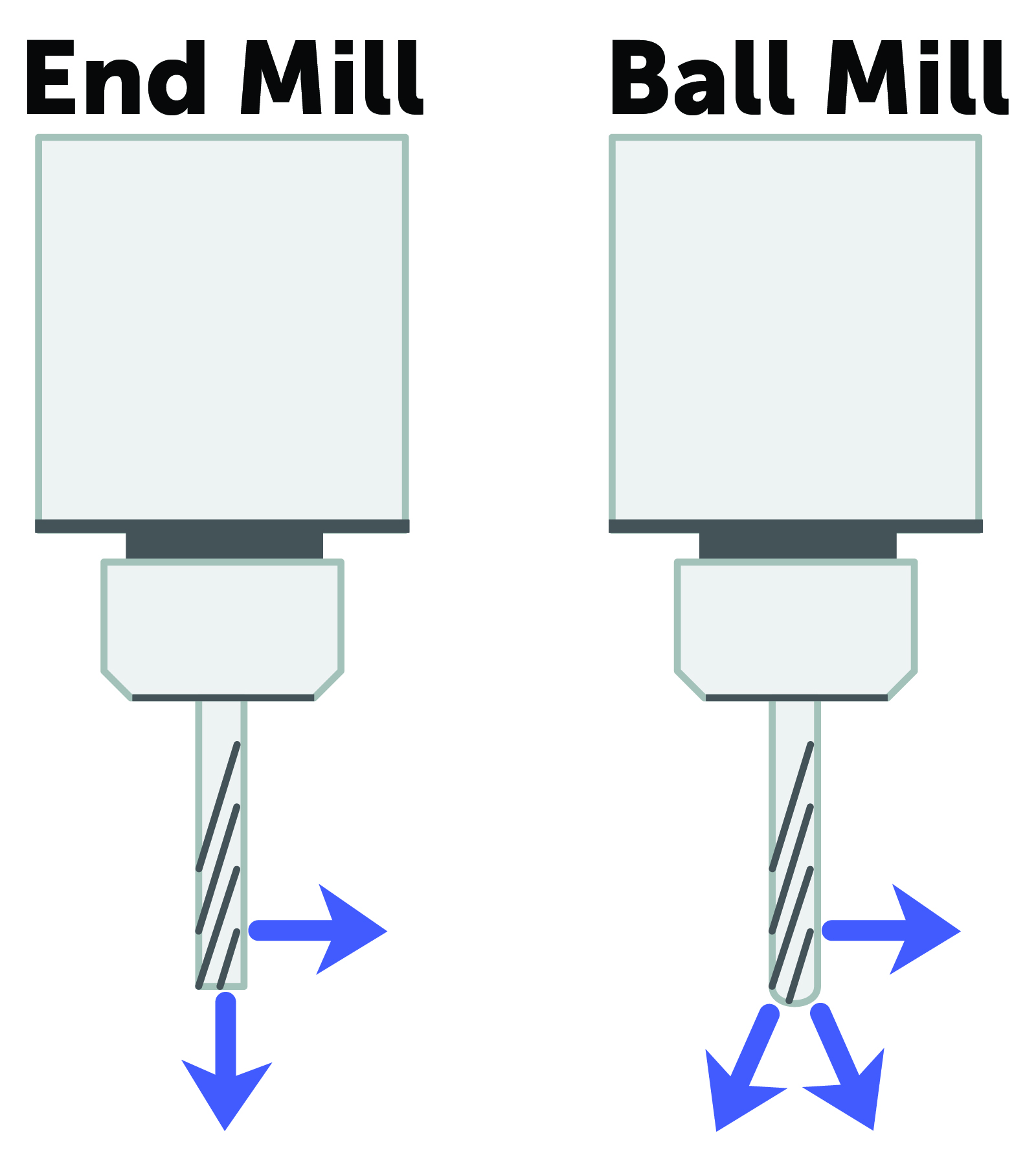
To cut cleanly, this vector must be parallel to the normal vector part surface. This means the tool must be oriented in 3D space to align the cutting vector and the surface vector. Finally, the tool must be long enough to reach the bottom of the cut.
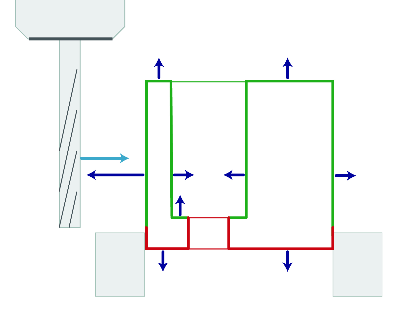
Setups
A setup includes securing the material in the correct orientation in the fixture and installing the tool. The number of setups is determined by the number of orientations needed to attain complete reachability for all surfaces and the degrees of freedom of the CNC machine.
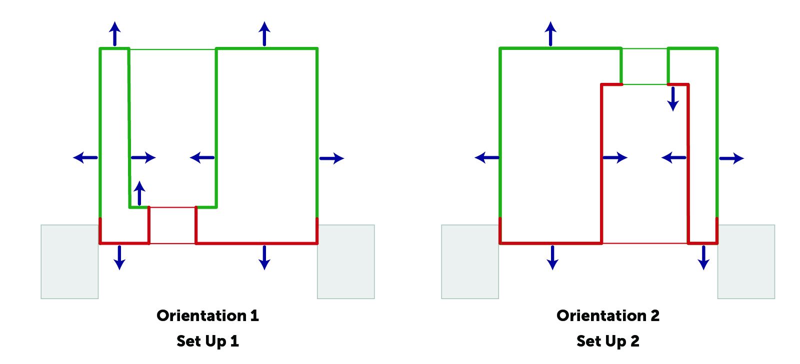
For example, a 3-axis machine can only align to one orientation per setup, while a 5-axis machine can align with many different orientations. So a part with machining on three adjacent faces would require three setups for a 3-axis machine but only one for a 5-axis machine. Manufacturing effort scales with the number of setups needed.
Part Stiffness
Part stiffness is determined by a combination of part geometry and material. It is a measure of how resistant the feature is to deformation from the machining process. The causes of deformation are:
- Dynamic cutting forces from the tool
- Static clamping force from the fixture
Stiffness is three dimensional, so a feature may only be weak in one dimension and strong in the other two. Part stiffness must also be maintained throughout the entire machining process.
Chatter
Chatter is the vibration of the machine-tool system and the part-fixture system. If there is a harmonic mismatch between the two systems, then cut quality will decrease. This results in wider tolerances and inconsistent surface roughness. The frequency of resonance is determined by the geometry of the systems, the cut width, and the spindle speed.
ADD graphic
Part Size
Part size is set by the bounding box that fully encloses the part.
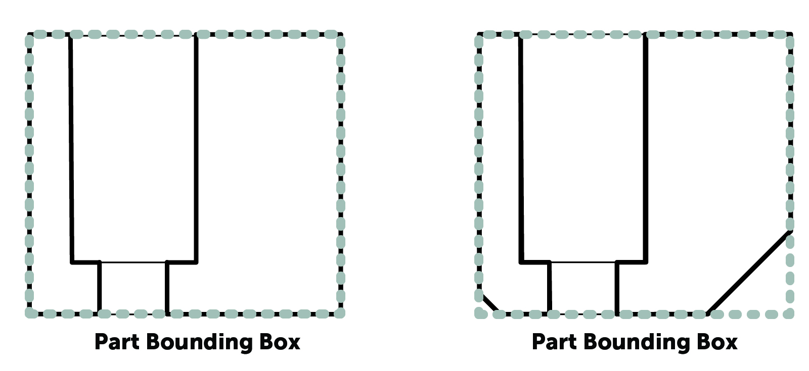
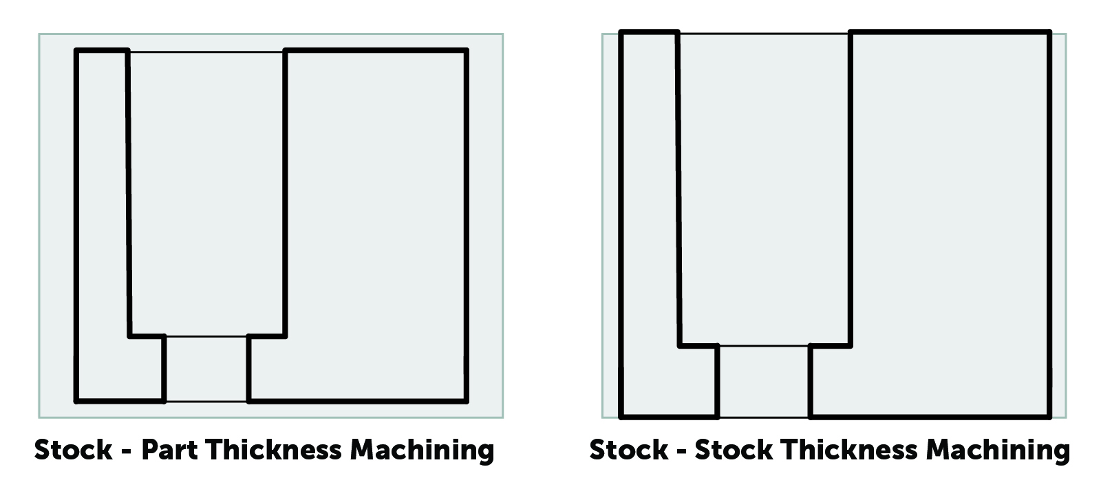
The stock material geometry must fully enclose the part bounding box. There are two different options for doing this.
The first is to oversize the stock and machine down to the exact part thickness. A general rule is to set the stock size to the part bound box plus 0.25in [6.35mm]. This method requires a for a facing pass on all the faces but allows for an arbitrary surface roughness.
The other option is to design the part to match a stock thickness. Using stock thickness can simplify machining, especially for thin thickness. However, the stock surface finish and tolerance must be acceptable for this method to be viable.
External Removed Material Ratio (ERMR)
The external removed material ratio is the volume of material remaining after machining to the volume of the original stock:
Part Bounding Box Volume / Stock Volume
This ratio measures how much excess stock there is between the bounding box of the part and the stock. The higher this ratio is, the more inefficient the machining process is, as the mill has to hog away more material.
Internal Removed Material Ratio (IRMR)
The internal removed material ratio is the volume of the part to the volume of the part bounding box:
Part Volume / Part Bounding Box Volume
This ratio measures how much material is removed from inside the part to get to the final geometry. The higher this ratio is, the more material has to be hogged out and the higher the manufacturing effort. In addition, high ratios indicate that the part could be affected by warping. The severity of this issue is material dependent. Warping is caused by differential friction heating during machining or by imbalanced residual stress in the material. The more asymmetric the geometry of the part is, the more it will be warped by residual stresses. Thinner parts are also more likely to warp from heat caused by machining.
CNC Machining Phases
The CNC machining process has three phases:
- Facing Pass (Optional) – The surface is machined down to the specified overall thickness.
- Rough Pass – A high speed, lower precision, high chip load pass for quickly removing the bulk material.
- Finish Pass – A slow speed, low chip load pass to set the final dimension of the part. This pass also determines the surface finish. Fillets are machined at this time as well.
Residual Stress
After a stock material is formed, the outside cools faster than the inside. As the inside cools, its volume changes and puts pressure on the outside of the material causing stress to build up. This stress is invisible because the symmetry of the cooling process balances the stress. The magnitude and distribution of residual stress is highly dependent on the manufacturing method of the stock. For example, rolling and annealing processes result in lower stress than extrusion.

The machining process removes material and creates an imbalance in these stresses. These stress forces can be great enough to warp the material. Unfortunately, warping can not be compensated for by running the machine slower because it is intrinsic to the material. Warping is a greater risk if the stock material is not machined symmetrically.
Cut Force
As the tool cuts the material it exerts a force on the part and the part exerts a force on the tool. A simplified view is shown below.
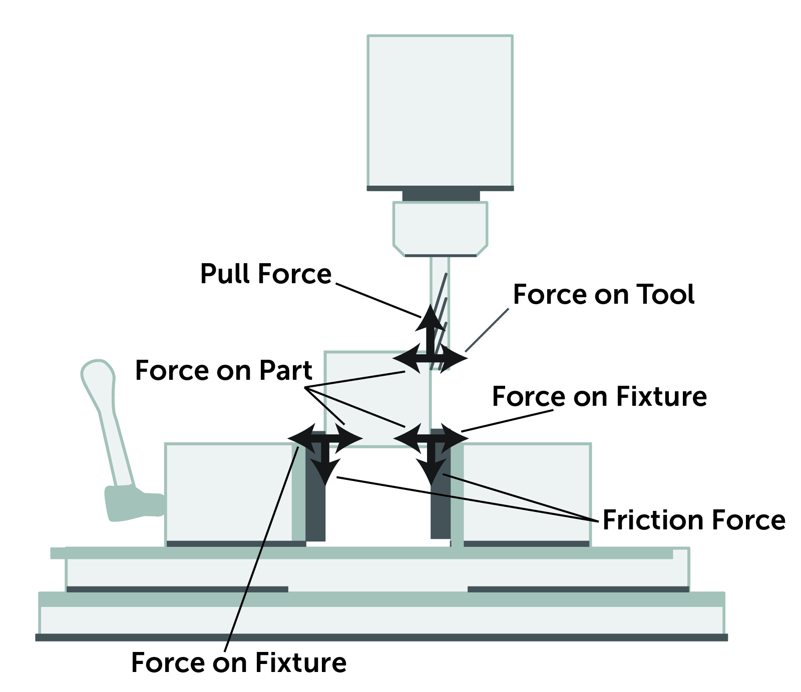
The higher the chip load on the tool, the greater the forces and the greater the deflection of both the tool and the material. Tool deflection is an issue because it reduces the quality of the surface finish and the precision of the cut. Material deflection is an issue for thin geometries because they warp or deform, reducing tolerance precision. Reducing the chip load reduces the cut load, which increases precision, but also increases machining time. Fixture forces can also deform the part and reduce accuracy and surface consistency.


