Module Overview
This module explores how to reduce effort in the most complex designs that appear in the aerospace, medical, and robotics industries. It specifies risk mitigation strategies for high precision, high geometric complexity, and extreme part sizes.
YOU WILL LEARN
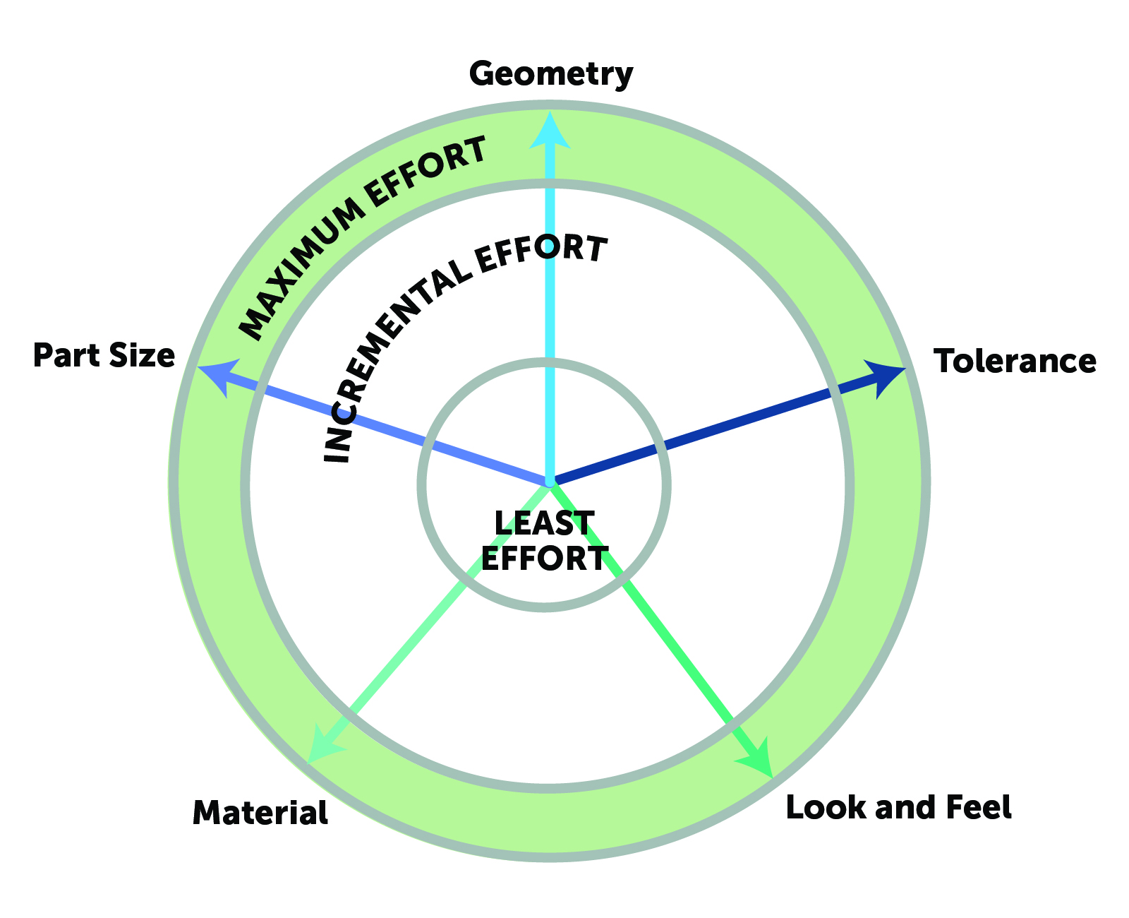
- When design parameters transition into the max effort region.
- Techniques for reducing effort, even at the edge of manufacturability.
- When to transition from CNC machining to another manufacturing process.
Mechanical Design at the Edge CNC of Manufacturability
In the previous modules, the focus of DFM was on keeping overall effort to a minimum and keeping the design well within the manufacturability zone of CNC machining. This module will focus on applications that demand a design engineer push CNC machining to the limits of what is possible.
Optical, aerospace, and medical products have very demanding requirements, including high precision, large scale and miniature part sizes, and complex geometries. These advanced design requirements have to be matched by advanced machining techniques, including 5-axis machining, precision machining, and large-scale or miniature machining. But even when engineering complex mechanical designs, it is possible to reduce the effort required.

Advanced design requirements push the machining process to the edge of its viability. Advanced requirements are often necessary to meet performance goals, but they are associated with exponentially increasing manufacturing effort. Additionally, at the edge of manufacturability, there is a larger risk the final part will be out of specification. Mitigating this risk is the key part of least effort manufacturing in this region.
CNC Machining of High Precision Mechanical Designs

Some examples of high precision parts are:
- High part count assemblies
- Alignment of optical components
- Sealed interfaces
- Bearings and other moving mechanisms
Tolerance can be for linear such as length, width, and position, or GD&T dimensions, such as surface flatness, parallelism, or perpendicularity. The crossover where effort starts to accelerate is ±0.005 in [0.125mm] at 3 mm length. At these tolerances, any deviation is significant—especially if the controlled dimension is machined from two different setups. It is difficult to maintain registration accuracy between setups because the change process is manual.
To reduce effort, limit very tight tolerances to as few dimensions as possible. You should also aim to design features with relative tolerances, so both features are machinable without changing setup. Increases in the stiffness of the tool-machine-part system also reduces effort because it minimizes errors during machining. This includes using tools above ⅛ in [3.18mm], to minimize deflection, and minimizing pocket depth, to increase tool stiffness. Finally, order additional quantities than you need, to compensate for any parts that are out of tolerance.
Transitioning to Grinding, Honing, Lapping, or EDM
Fictiv is capable of hitting CNC machining tolerance of ± 0.0007 in [0.020mm] for metal and ±0.1in [2.54mm for plastic]. If the design requires tolerance below this threshold, then the process must change to grinding, honing, lapping, or EDM, depending on the target tolerance.
High Geometric Complexity Mechanical Design

Complex geometries are required for many applications, such as propellers/impellers or engine blocks. These geometries are characterized by internal or obstructed non-orthogonal surfaces, with continuously varying surface normals. This type of design geometry can only be manufactured using 5-axis CNC machining.
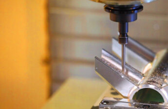
5-Axis, Square End Mill*

As mentioned in Module 2, the use of 5-axis machines drives significantly higher manufacturing effort, compared with 3-axis machines, because fewer machine shops have them, and their availability is lower. Additionally, 5-axis machines require operators with more advanced expertise.
Design geometries in the region can also have a very high removed material ratio for applications where weight is a concern. In those situations, be aware that internal stress warping can be significant, so you should maximize wall thickness as much as possible.
Edge Counts and Fillets
Another effect of complex geometry is a high number of edges. As edge counts grow, even deburring time can become a factor. To minimize effort, only fillet when absolutely necessary, and specify breaking for the rest of the edges. Where fillets are necessary, use the largest radius possible, or specify a minimum tolerance only. These options give the manufacturer the most freedom to choose the simplest finishing method.
Transitioning to 3D Printing
5-axis CNC machining can realize immensely complex geometries, but there are limits to the process. Machining internal surfaces requires a way for the tool to contact the surface from the outside. This means geometries with extreme undercuts or enclosed chambers are not accessible even for a 5-axis CNC. Also, as tool reach grows, the tool weakens, and accurate cutting becomes impossible. Geometries with these characteristics are not machinable, and 3D printing or molding must be used.
CNC Machining Extreme Part Sizes

Large Parts
Large parts are required in many industrial applications, such as motors and structural components. These parts are high effort because material sourcing is harder, they are challenging to setup and fixture, and large parts often require a long tool reach.
To vastly reduce the manufacturing effort, break the large part into an assembly. Though this creates three jobs, instead of one, it is actually faster and cheaper to produce. If the part cannot be broken apart, design to an existing stock size, to simplify sourcing and reduce material cost. Also, for large part sizes, setup is very challenging and takes significant time, so it is even more important to minimize setups.
Transitioning to Super Scale CNC machining
Above lengths of 36 in [914.4 mm], it is hard to find premade stock. Custom made stock is possible to procure, but the costs are extremely high. Also, at these sizes, the material will not fit standard CNC machines, and specialized large format CNC machines are needed.
Small Parts
On the small end, part sizes below 1 in [25.4 mm] in the long dimension are seen in many medical applications, as well as semiconductor and robotics applications. Both the parts and the tools are fragile at these scales, and it requires more effort to manage the cut forces precisely. Incorrect fixturing can easily deform the part, and tools are especially prone to deflection and breakage. Also, tool life is greatly reduced. For these very small parts, design around existing stock, if possible, and minimize volume machined to reduce effort. Additionally, it is best to have only one dimension less than 0.1 in, if possible. Intentionally designing in parallel surfaces can also greatly simplify fixturing.
Transitioning to Micromachining and EDM
For part sizes below 0.5 in [12.5 mm] in the long dimension, or feature sizes below 1/64 in [0.4mm], CNC machining is no longer infeasible, and another process like micromachining or EDM is required.
Conclusion: High Complexity and Manufacturing Effort
As design complexity approaches the edge of manufacturability for CNC, effort begins to grow exponentially. In this region, it is still possible for designers to compensate for the manufacturing challenges and reduce effort. Reducing effort helps mitigate the risks of manufacturing and increases the chances of successful manufacturing. See the checklist below for techniques to reduce effort.
Maximum Effort DFM Checklist for CNC Machining
Download the checklist as a handy reference guide here!
Tolerance
- Define tight tolerance for only for critical dimensions
- Maximize the stiffness of the machine-tool-fixture-part system
- Select maximum tool sizes
- Minimize cut depth
Geometry
- Manufacturing effort jumps significantly for geometries that require a 5-axis CNC machine. Any subsequent increase in complexity only incur an incremental effort increase.
- Edge and surfaces multiply exponentially increase deburring effort.
Part Size
- For large parts
- Break large parts into assemblies reduces effort
- Design part around existing stock material
- For small parts
- Minimize cut depth
- Design parts around existing stock sizes
- Design surfaces for fixturing
Get Expert DFM Guidance on Your Designs
We hope this course helps you to be more efficient and strategic with your designs, so they are more optimized for least effort CNC machining. Of course, it is still important and beneficial to get DFM feedback on each of your custom part designs as a part of your product development process. Even the most experienced engineers should still seek feedback from their manufacturing partners for optimal manufacturability.
Through Fictiv’s Digital Manufacturing Platform, you get free DFM feedback for every part quoted for CNC machining. With every CAD model uploaded to the platform, you get automated DFM feedback generated by the platform, and you can also engage with our manufacturing experts to understand the DFM in order to alter your parts if necessary. We have a team of manufacturing engineers who will even manually review complex parts to provide customized DFM as needed.
Create your free account for expert DFM here!


