Module Overview
This module introduces the “effort” model for understanding the factors that drive CNC machining cost, lead time, and risk. It shows how design parameters map to manufacturing effort and the corresponding rule set for designs that are cheapest and fastest to produce
YOU WILL LEARN
- The definition of manufacturing effort
- The main design parameters that affect manufacturing effort in CNC machining
- The rules for designing for least effort including tolerance, part geometry, part size, materials, and look and feel
Going Beyond DFM 101 in Manufacturing Design
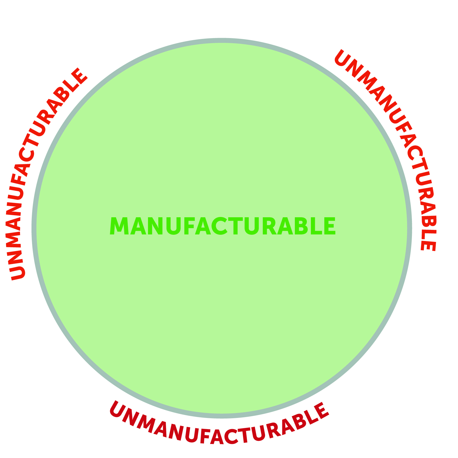
Design for manufacturability (DFM) starts with the basic test of whether a design is manufacturable or not. These rule sets, as represented in the Fictiv CNC Machining design guide, provide essential guardrails to the manufacturing design process which prevent catastrophic problems.

However, passing manufacturability checks does not mean that the design will be successful. Making the wrong decisions can lead to reachability issues, extra setups, surface defects, or other machining challenges, which translate into higher manufacturing costs and longer lead times. Many of these problems are avoidable through appropriate choice of design specification. The key to understanding the effect of different design choices is to understand how different designs require different levels of effort to manufacture.

Manufacturing Effort: A measure of time, care, and challenge to manufacture a design.
Least Effort Manufacturing Design
Designing for the least amount of manufacturing effort is the next level goal of DFM. Least effort scales with the complexity of the design requirements. So, for example, a design for controlling fluid flow will have a higher effort than a design of a simple test fixture. The key is to design so there is no unnecessary effort in the manufacturing process.
Least effort design is especially important if the design will be taken to production. In production, every instance of unnecessary effort translates into lower margins, lower production volume, and in the worst case can render production uneconomic. Therefore least effort manufacturing principles should be incorporated into the design process from Day 1.
The Five Design Parameters of CNC Machining Effort
There are five design parameters that determine manufacturing effort for CNC machining.

- Geometry: The shape of the part and the corresponding number of setups required to machine it.
- Tolerance: The linear tolerance or GD&T for the specified geometric relationship.
- Part Size: The overall size of the bounding box for the part.
- Material: The material the part is made of.
- Look and Feel: The number of surfaces and edges that have additional machining beyond that default output of the machining process.
Mapping Design Parameters to Manufacturing Effort
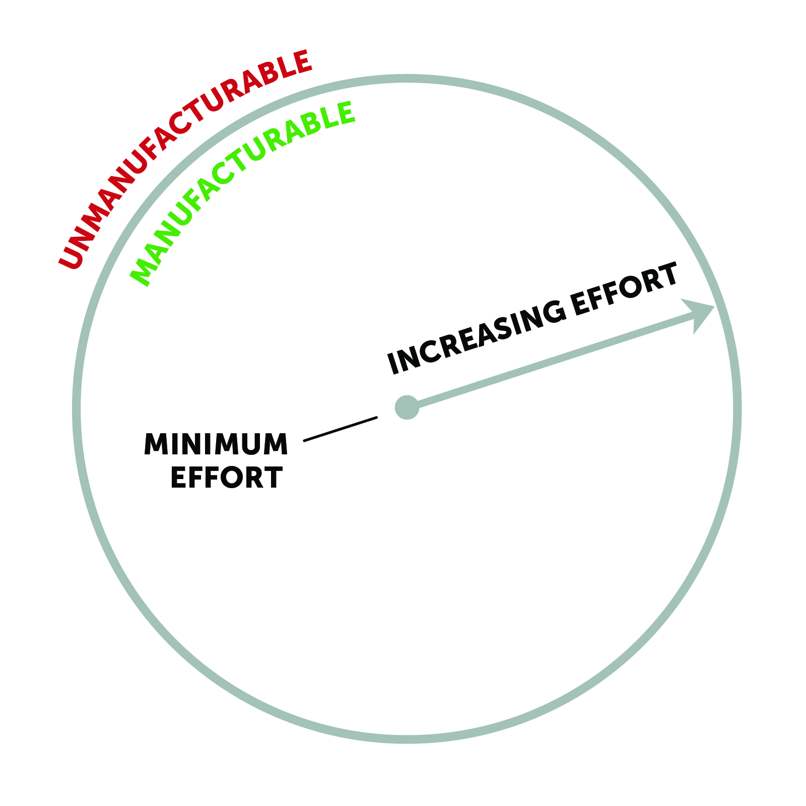
It is possible to map each design parameter to its corresponding level of effort. In some cases, multiple regions of the same parameter map to the same effort region. For example, both very small parts and very large parts map to the max effort region.

The manufacturable zone can be broken down into three regions.
- Least effort: This region is where costs and lead times are the lowest.
- Incremental effort: This region is where some extra effort is required and where cost and lead times increase incrementally.
- Maximum effort: This region is on the edge of what is manufacturable and is where maximum effort is required. In this region cost and lead times increase exponentially.

High effort designs map to the extreme edges of the manufacturable region, while low effort designs map to the center. This heuristic reveals where the risk is in the design and where effort could potentially be reduced.


Least Effort for CNC Machining
The least effort region for CNC machining is the region of lowest cost and fastest lead time. Any machine shop should be able to manufacture least effort designs. By pushing as many design parameters into this region as possible, designers can increase speed, lower cost, and reduce risk. In general, designs that are least effort are simpler and have no special requirements. Common low-effort parts include fixtures and brackets. Below is a description of the least effort region for each parameter.

Least Effort Tolerances

For tolerance, the easiest option is to leave the tolerances set by the stock material. For features that are machined, ISO 2768, medium is a good balance of what is easily achievable with standard CNC machines and what is necessary for normal functional parts.
Least Effort Part Geometry

Design to Stock Material Geometry
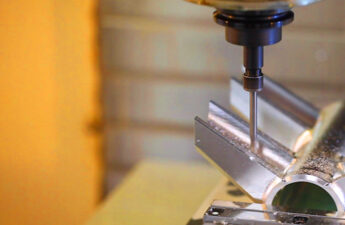
Least effort part geometry uses a stock geometry and makes the least amount of adjustment to it. Stock material comes in bars, sheets, rods, and tubes as well as other specialized shapes. Stock materials can also make certain geometries low effort–for example, using a tube and leaving the inner diameter as stock allows for an arbitrary hole depth greater than the normal 10x tool diameter guideline. If stock material is not used then gun drilling is required, which adds effort.
Design for Reachability
To machine a surface geometry, it must be reachable by the tool. This means that there is an orientation of the CNC machine and tool where the normal vector of the cutting surface is parallel to the normal vector of the part surface. Below is an example of reachability for a square end mill (shown in 2D for simplicity).


For least effort, limit geometries to what can be reached by a 3-axis machine with no 3D machining. Least effort designs are characterized by orthogonal surfaces that intersect at 90°.


Least Effort CNC Tooling
Different tool geometries have different surface normals that make different surface profiles reachable. For least effort, tool geometries should be limited to:
- Square End Mill
- Chamfer Mills
- Ball End Mills
- Drills
Minimize Fixture Setups
If a part geometry is fully reachable, it will still require more than one setup to machine every surface. Least effort geometries should require no more than two setups. Parts should also have two parallel surfaces perpendicular to each machinable side, so that standard fixturing is possible.

Part Stiffness
Another very important consideration when manufacturing to a specific tolerance is the stiffness of the part during machining. Forces on the part from the tool and the fixture can cause deformation and chatter. To compensate for these issues, machinists must take extra care during fixturing and run machines slower to reduce cut forces. To reduce effort, use parts with symmetric geometries that distribute loads evenly and keep wall thickness above 3/8in [9.5mm].
Warping Risk
Warping is another risk if there are thin walls in the geometry. The internal removed material ratio (IRMR) and external removed material ratio (ERMR) can show if this may be an issue or not. The higher these ratios are, the more likely that deformation or warping will occur. Keeping the ERMR < 80% and the IRMR < 30% can help prevent these issues.
Least Effort Part Size

Fixturing is one of the major contributors to manufacturing effort. Keeping part size between (0.25 in x 2 in x 2 in) and (6 in x 6 in x 6 in) means that the part should fit in the standard fixture machine shops have available. Manufacturers will have different standard sizes so it is always useful to check what the manufacturer has readily available. At Fictiv, parts are always matched to the closest stock size. Stock usually comes over sized in one dimension and then is cut down with a bandsaw. Below are standard size that are generally available:
Sheets
| Size [in] | Thickness [in] | Tolerance Range |
|---|---|---|
| 2in × 48in | 1/4in – 2in | ±0.002 to ±0.009 |
| 4in × 48in | 1/4in – 1/2in | ±0.002 to ±0.009 |
| 6in × 6in | 1/4n – 1 3/4in | ±0.002 to ±0.014 |
Bars
| Thickness [in] | Width [in] | Tolerance |
|---|---|---|
| 1/4in | 2in – 6in | ±0.0012 |
| 5/16in | 2in -3in | ±0.008 |
| 3/8in | 2in – 6in | ±0.008 |
| 1/2in | 2in – 6in | ±0.009 |
| 5/8in | 2in – 6in | ±0.009 |
| 3/4in | 2in- 6in | ±0.001 |
| 7/8in | 2in | ±0.01 |
| 1in | 2in – 6in | ±0.012 |
| 1 1/4in | 2in – 6in | ±0.012 |
| 1 1/2in | 2in – 6in | ±0.014 |
| 2in | 2in – 6in | ±0.024 |
| 2 1/2in | 2 1/2in – 5in | ±0.024 |
| 3in | 3in – 6in | ±0.024 |
| 4in | 4in – 6in | ±0.034 |
Rods
| Diameter [in] | Tolerance |
|---|---|
| 2in, 2 1/8in, 2 1/4in, 2 3/8in, 2 1/2in, 2 5/8in, 2 3/4in, 2 7/8in, | ±0.034 |
| 3in, 3 1/8in, 3 1/4in, 3 3/8in, 3 1/2in, 3 5/8in, 3 3/4in, 3 7/8in, | ±0.034 |
| 4in, 4 1/4in, 4 1/2in, 4 3/4in | ±0.034 |
| 5in, 5 1/4in, 5 1/2in, 5 3/4in | ±0.034 |
| 6in, 6 1/4in, 6 1/2in, 6 3/4in | ±0.104 |
Least Effort Materials

The least effort is defined by how easy the material is to machine. Machinability is made up of multiple parameters, but the major drivers are thermal conductivity, hardness, and chip formation. The list of least effort materials is shown below and is organized by the material strength.
- Plastic – Delrin
- Soft Metal – 6061 Aluminum
- Hard Metal – 1018 Steel
Least Effort Look and Feel

Surface Roughness
An easily achievable default roughness is 63μin Ra or 1.6μm Ra and higher. At Fictiv, this is the standard, unless otherwise specified.
Fillets
Fillets are easy to add into CAD, but they just as easily increase manufacturing effort. The key is to know what fillets you need and what you do not. By default, the edges parallel to the tool will be filleted for a given setup and edges between compound surfaces. These are intrinsic fillets and are unavoidable. Fillet radius is set by the finish tool diameter. To minimize effort, size finish tools for greatest efficiency, and then set the fillet radius to match that diameter. For all other edges, add a note to your drawing to “break all edges”. This instruction gives the manufacturer the freedom to round those edges in the simplest way possible.
Conclusion: Minimizing Effort in CNC Machining
Each design decision you make ultimately results in a machinist programming a tool path, determining feeds and speeds, loading material into a fixture, and creating the part. Though each of these tasks may be small, the effort required can add up to high costs and long lead times that can put projects at risk. Understanding how to avoid unnecessary effort is especially important for designs in the Least Effort region of the manufacturable zone. See the list below for the rules for keeping designs within this region.
Least Effort DFM Checklist for CNC Machining
Download the checklist PDF as a handy reference guide here!
Least Effort Tolerance
- Design to ISO 2768 medium standard
Least Effort Geometry
- Design around a stock material
- Remove as little material as possible
- Design for 3-axis machine without using 3D machining
- Use a maximum of 2 setups
- Design so that there are parallel surfaces for each set up
Least Effort Part Size
- Keep part size between 0.25in X 2in X 2in and 6in X 6in X 6in
Least Effort Material
- The following are the best least effort material options for their respective categories:
- Plastic – Delrin
- Soft Metal – 6061 Aluminum
- Hard Metal – 1018 Steel
Least Effort Look and Feel
- Specify a surface roughness of 63μin Ra or 1.6μm Ra
- Define only intrinsic fillets
- Size fillets to largest tool size possible
- Specify “break all edges” for all other external edges in your drawing


