








Time to read: 9 min
Prototype testing is the definitive bridge between digital simulation and commercial manufacturing reality. While finite element analysis (FEA) can predict theoretical stress distribution, physical testing is necessary to uncover hidden failure modes, validate material properties, and ensure regulatory compliance. A rigorous testing framework ensures that design flaws are identified and corrected when the cost of engineering changes is lowest, preventing quality and yield issues during mass production.
Begin with the End in Mind: Your Requirements Document
What does the design need to do? And how will you know if it’s achieved that goal? Your product requirements document (PRD) should be specific and include test standards for verification of each requirement.
For instance, let’s say you’re creating a case, and it needs to be waterproof. Saying a case is “waterproof” on its own is an almost meaningless requirement. Does that mean it can withstand the rain? What if you drop it in the pool? Can you take it deep sea diving?
A vague requirement like “waterproof” or “durable” cannot be validated on the test bench. Instead, engineers must translate product requirements into quantifiable engineering metrics mapped to international testing standards, such as ASTM or ISO protocols. For example, a rugged waterproof enclosure must be defined by an explicit Ingress Protection (IP) rating, such as IP67, which specifies exact submersion depths and durations.
And if you’re not quite sure how severe to make your tests, consider deferring to an international standard: ASTM has hundreds of different test standards, covering everything from hardness to UV resistance to drop resistance. Just try googling “ASTM standard” and whatever area you’re thinking of; you’ll be sure to get more detail than you thought possible.
With uncommon requirements, you may need to get a little more creative. In the above example of a case, let’s also say that one of the requirements is that the buttons need to be designed for activation by someone wearing gloves. That’s a nebulous requirement, but you can do some experiments ahead of time on minimum size, minimum protrusion, and maximum depth of activation, which allows that to be easy, then incorporate those findings into the requirements document.
Isn’t this all a lot of work to do before you even begin your design? Well, yes. But it’s much less work than completely throwing away a design and restarting because your design doesn’t function well. Just like in high school Calculus, the key to making exam day easy is front-loading the work earlier in the semester.
Testing Design Elements
And speaking of front-loading work (because apparently, I’m old enough to lecture on that now), another way to make final tests more predictable is to test each element of your design separately. Waiting till you have a complete design and then running all the tests is an almost surefire recipe for failure. Instead, look at each function of the design, and ask how you can test just that function, or even just that function on one area.
Going back to the waterproof case design, if you wanted to create a new GoPro housing, you would want to separate out each unique button design and test that for waterproofness separately, and then create a case with no buttons to test how waterproof the main seal is. If you test it all at once and have a leak, you’ll have no idea which area to improve; by testing the elements out one at a time, you can perfect each element separately before testing the whole.
In the same way, tease apart the functions. You don’t need to do a drop test on the fully assembled hundred-thousand-dollar-with-functioning-electronics version of your company’s new product and shatter all the hard work of the electronics team (unless you have an enemy over there at whom you need to get back, in which case, shatter away, and maybe add in a sledge-hammer test, too); drop test just the mechanical housing to see how it holds up, first, before seeing how it dampens the electronics.

Less dramatic tests benefit from sectioning, too. On a recent housing, my client wanted a very specific feel for the snap-fit closures for the case, but there was no reason to print out the entire, large case for each test: We cut just the ends of the case, with the snap fits, and have been running tests on geometry for just those parts, saving hundreds and still getting the function just right.
You can do something similar for even the non-technical tests. A final prototype is amazing to get a true feel of the design, but once you’ve gotten team approval for the feel and aesthetics of the design with your CAD models and renderings, try a cheap 3D print to make sure you haven’t missed anything before you get too far into the design.
Sectioning your parts and function tests does bring up a small conundrum, though: Each of these tests would likely benefit from a different material. How do you choose what to material to use for your prototypes?
Choosing Materials for Your Tests
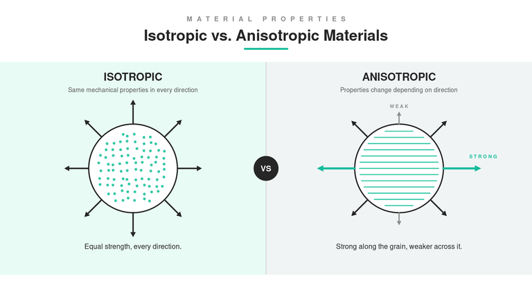
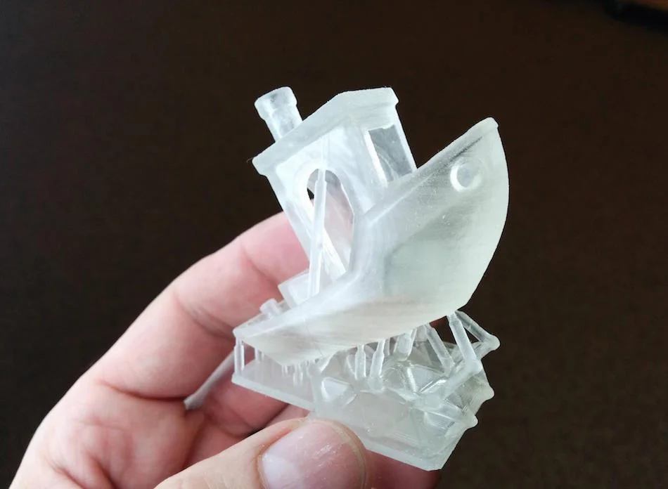
The validity of your test data depends entirely on matching the material properties and manufacturing process of your prototype to your specific testing objectives. While early-stage form, fit, and ergonomic validation can leverage rapid additive manufacturing technologies like SLA, FDM, or SLS, these photopolymers and layered thermoplastics exhibit significant anisotropy and lower structural thresholds.
For functional testing of complex mechanical interactions, material data sheet parameters must be meticulously matched to design intent:
- Snap-Fits and Living Hinges: Validating flexural deflection requires a prototype material with a Modulus of Elasticity and flexural yield strength that closely mimic the final mass-production resin. Testing these features with brittle 3D-printed resins leads to premature structural failure, whereas CNC-machined engineering plastics or SLS nylons yield accurate stress-strain behavior.
- Sealing Surfaces and Gaskets: To achieve reliable fluid or dust ingress testing, the prototype material must support fine surface finishes and high dimensional stiffness to ensure uniform gasket compression. Rough surface finishes (Ra) or layered boundaries from lower-resolution prints create micro-leak paths, making CNC milled surfaces or high-resolution SLA prints mandatory for final seal verification.
- Sourcing and Cost Optimization: To get the most out of engineering budgets, sourcing teams should utilize commercial-grade, non-certified materials for initial verification cycles. Save premium medical-grade, flame-retardant (UL94-V0), or fully certified material lots strictly for final compliance and regulatory testing phases.
For rigorous mechanical, thermal, or cyclic fatigue testing, engineers use subtractive and formative prototyping processes to ensure data fidelity. CNC-machined prototypes in production-grade engineering plastics (such as Delrin, PEEK, and Polycarbonate) or metals (such as Aluminum 6061-T6 and Stainless Steel) provide true isotropic properties and precise tolerance stack-up validation.
Similarly, sheet metal fabrication is required to test structural chassis rigidity, drop-impact structural integrity, and thermal dissipation, while low-volume urethane casting bridges the gap for testing elastomeric components and multi-material overmolded designs before investing in hard production tooling.
Prototype Material and Process Capability Matrix
| Prototyping Process | Representative Material Options | Primary Testing Applications | Material & Testing Trade-offs |
| 3D Printing (FDM, SLA, SLS) | ABS, Polycarbonate, Nylon, Photopolymer Resins | Spatial assembly checks, cosmetic reviews, and non-structural form validation | Highly anisotropic; layered boundaries introduce structural shear vulnerability |
| CNC Machining | Aluminum 6061/7075, Stainless Steel, Delrin (POM), PEEK, ABS | High-stress structural fatigue loading, precise dimensional tolerance stack-up analysis, and thermal dissipation testing | Delivers true isotropic mechanical properties matching production materials; restricted only by tool path accessibility |
| Sheet Metal Prototyping | Aluminum, Stainless Steel, Cold Rolled Steel (CRS), Copper | Enclosure drop testing, electromagnetic interference (EMI/RFI) shielding validation, and structural chassis rigidity | Provides production-level material performance; prototype geometry is limited by standard brake and forming design rules |
| Urethane Casting | Specialized Polyurethanes (simulating ABS, Polycarbonate, EPDM) | Fit testing, aesthetic and ergonomic qualification, and elastomeric seal or gasket verification | Delivers uniform isotropic performance and realistic cosmetic finishes, but polymers differ from final injection-molded resins |
Running and Recording Prototype Tests
Recording test parameters with absolute traceability is what turns a casual workshop experiment into a legally and technically defensible engineering asset. When a prototype fails downstream, debugging, root cause analysis, and regulatory compliance (such as FDA or ISO certification audits) depend on the integrity of your testing history. Rather than relying on static, disconnected spreadsheets, engineering teams should align their test logs with an established Test Failure Modes and Effects Analysis (T-FMEA) or a dedicated Test Execution Matrix.
To eliminate noise and ensure data fidelity, a rigorous test run should isolate variables by enforcing three operational baselines:
- Instrumentation Calibration: Before starting telemetry, establish a known baseline for your test setup. Uncalibrated load cells, drifting thermocouples, or structural flexing within the test fixture itself introduce systematic errors that will skew your mechanical data.
- Statistical Sample Size: Testing a single prototype (n = 1) produces an anecdote, not valid engineering data. To account for material batch variations and rapid prototyping manufacturing tolerances, define a minimum sample size—typically n=3 to n=5 for early engineering verification—to ensure your results are repeatable.
- Synchronized Telemetry Capture: Map your continuous data-log sensor readouts to a unified timestamp. This includes tracking strain gauges monitoring mechanical deflection, or surface thermocouples tracking localized thermal saturation.
Finally, if you are conducting destructive testing, static measurements won’t tell the whole story. Pair your sensor telemetry with high-frame-rate video positioned at the anticipated failure zones. Synchronizing visual fracture propagation directly with your load-cell data spikes allows your team to pinpoint the exact time, stress level, and geometric location of the initial structural yield.
Staging the Testing Cycle: EVT, DVT, and PVT Frameworks
Industrial hardware development relies on a phased validation framework to manage risk systematically. Testing strategies must evolve across three distinct pre-production builds:
- Engineering Verification Testing (EVT): Focuses on fundamental functional and mechanical validation. Protocols include core feature testing, initial thermal profiling, and preliminary electromagnetic compatibility (EMC) scans using early functional prototypes.
- Design Verification Testing (DVT): Focuses on reliability, environmental endurance, and design robustness. Prototypes built in the intended production environment are subjected to accelerated stress testing (AST), including thermal shock, humidity cycling, drop testing, and ingress protection validation.
- Production Verification Testing (PVT): Focuses on process capability and quality control. At this final stage, testing validates the manufacturing line itself, ensuring the factory can maintain dimensional stability and cosmetic acceptance criteria at full production speeds.
Learn more about development process models in our Stage Gate Product Development Guide.
Prototype Test Protocol and Staging Matrix
| Validation Phase | Primary Test Objective | Typical Prototyping Method | Applicable Standards |
| Early Concept | Form, fit, ergonomic placement, and spatial assembly checks. | FDM / SLA 3D Printing | Initial Dimensional Verification |
| EVT (Engineering) | Core functional performance, power delivery, and initial thermal loads. | SLS / Carbon DLS / CNC Machining | ASTM Mechanical Property Profiles |
| DVT (Design) | Environmental lifecycle, cyclic fatigue, drop impact, and ingress compliance. | Urethane Casting / Prototype Tooling | IP65/67, ASTM D4169 (Drop/Vibration) |
| PVT (Production) | Tooling wear, assembly yield optimization, and cosmetic consistency. | Production Injection Molding, Casting | ISO 2859-1 (Sampling/Acceptance Criteria) |
Understanding Prototype Test Results
Don’t think of a prototype failure on the test bench as a project setback; it’s a successful risk mitigation event before capital is deployed for production tooling. But the value of that failure depends entirely on the rigor of your post-test diagnosis.
When analyzing test data, engineers should avoid the trap of modifying CAD geometry immediately based on a single data point. Instead, determine whether the failure was systemic in the design or an isolated anomaly in the rapid prototyping process itself.
To systematically translate test anomalies into actionable design revisions, execute a four-part failure analysis protocol:
- Isolate Design Flaws from Manufacturing Defects: Before redesigning a feature, verify that the prototype was built to specification. In molded or cast parts, failures often stem from localized manufacturing anomalies—such as internal porosity, material contamination, or weak knit lines (where polymer flows meet). Conversely, if CNC-machined metal parts fail under identical load profiles across multiple samples, the root cause is likely a systemic design flaw such as an unexpected stress concentration or an incorrect tolerance stack-up.
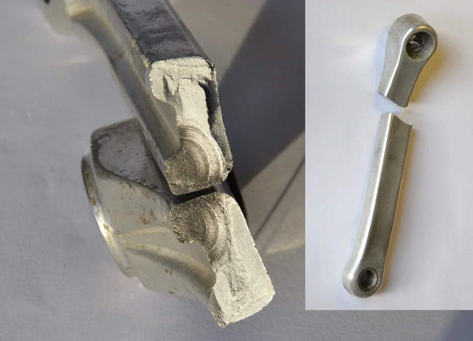
- Deploy Physical Root Cause Analysis (RCA): Move beyond digital data logs to examine the physical hardware. Utilize non-destructive evaluation (NDE) such as industrial CT scanning to check for internal voids or micro-cracks before sectioning a part. For destructive analysis, inspect the fracture topology under magnification. Identifying whether a failure mode is ductile (showing material elongation and tearing) or brittle (clean, sharp fractures) tells you exactly how the material behaved under stress.
- Audit and Filter Data Outliers: When a single test sample fails prematurely while others pass, do not simply average the data or discard the outlier. Conduct a thorough statistical check. Isolate whether the variance was caused by an uncalibrated test fixture, human error during setup execution, or a genuine statistical deviation in material performance that could manifest as a low yield rate in mass production.
- Close the Loop and Update Risk Matrices: An engineering change is incomplete until the lesson is implemented. Feed your findings directly back into your active Design Failure Mode and Effects Analysis (DFMEA). Update the severity, occurrence, or detection rankings for that specific failure mode, and document the explicit CAD or material modification implemented to mitigate the risk in the next build cycle.
Testing Your Design
At Fictiv, we are here to help source all the high-fidelity custom parts you need to execute rigorous prototype testing. Fictiv is your operating system for custom manufacturing that makes part procurement faster, easier, and more efficient. In other words, Fictiv lets engineers, like you, engineer.
Create an account and upload your part to see what our instant quote process, automated design for manufacturability (DFM) feedback, and intelligent digital platform can do for your next validation cycle. Whether you require rapid 3D printing for early functional checks or precision CNC machining for high-stress structural validation, we can deliver your custom components in as little as 24 hours!