Time to read: 8 min
If you’ve ever been to Fictiv HQ, either to pick up parts for one of our events, or simply just to say hi and chat about hardware, you may have seen our drone prototypes. For those unfamiliar with them, these prototypes are a series of material samples in the form of mini drone bodies and legs, as well as an assembled and functional CNC machined drone.
This project came out of our desire to develop a cohesive set of samples for both 3D printing and CNC machining. The initial requirements were vague, but the overall idea was that the samples needed to highlight the uses, advantages, and disadvantages of Fictiv’s standard materials for each process, as well as the processes themselves. In addition, individual samples should combine to form a functional product of some sort.
After quick brainstorm, the idea of a model drone was born, and in the three weeks that followed, we built a functional prototype. In the paragraphs below, I’ll highlight the drone design considerations, the challenges we encountered, and the lessons we learned as we developed and translated a singular design across a wide suite of materials and processes, in a short time period.
Why a drone?
Besides the fact that drones are awesome feats of engineering, why did we choose this product for something like material samples? The decision was based on a few criteria:
- Open-source design: A thriving community is developing drone and UAVs without IP restrictions. This rich knowledge base is a great source of inspiration and allows quicker development by tweaking existing models to suit requirements, rather than starting from scratch.
- Feature diversity: Drones are composed of both designed and purchased components. Those designed include features perfect for showcasing in a material sample, including organic geometry, overmolds, assembly features (fastener interfaces, snap fits), and mating surfaces.
- Ease of sourcing: All purchased parts for this project were harvested from a cheap mini drone found online. With the electromechanical portion of the design fixed from the start, the body could simply be designed around this, as long as the general size and form factor remained the same (the overall size was scaled up slightly).
- Self-defining requirements: Rather than choose some random product, design requirements for a drone are fairly predetermined. We needed it to have a body and legs; the harvested components had to fit inside; all parts needed to assemble in a straightforward manner; and hopefully, in the end, the drone would fly!
Breaking up the model
It would have been straightforward to copy the purchased mini-drone design, but this would have taken all the fun out of the project and not been ideal for a couple of reasons.
First, the purchased drone body is made entirely out of injection molded plastic. Our material samples would all be 3D printed and CNC machined, which have different design considerations and constraints; therefore, the models need to differ to account for manufacturability in these processes.
Second, the purchased body is only made of upper and lower halves, including legs. In order to showcase more features, strengths, and weaknesses of each of Fictiv’s materials, I decided to split the legs off from the body.Below is an overview of each of the designed parts. For each, there is a list of the materials in which the part is produced, an explanation of the features included, and some considerations and best practices behind their individual designs.
Body Top

Materials:
Notable Features/Challenges:
- Organic geometry
- Screw bosses/heated inserts
- Snap-fit mates
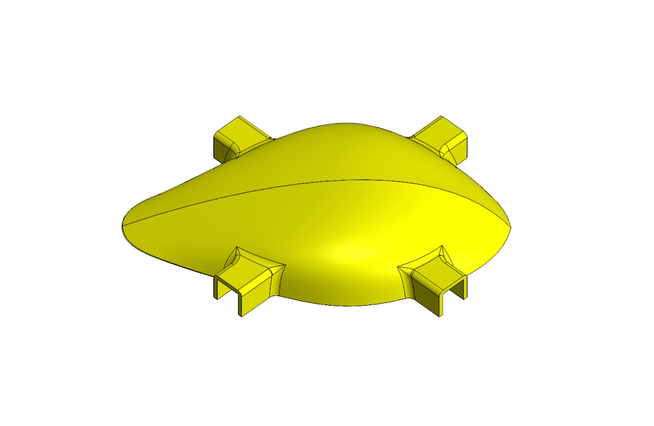
The top half of the drone body, though organically shaped (which should generally be avoided to save costs in CNC, unless it is absolutely necessary), is otherwise simple in design. On its underside are three large screw bosses, used to attach the bottom half of the body, and two small screw bosses, to which the control board fastens.
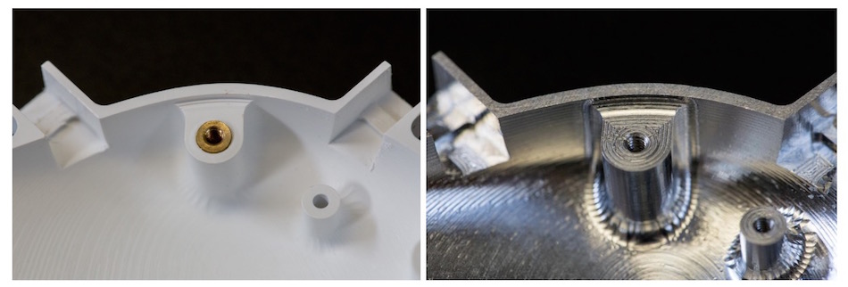
In the 3DP and CNC ABS versions, the large bosses were designed to have press-in and heated inserts, to create robust threading that could be used repeatedly (plastic threads tend to wear over time); on the CNC aluminum version, these bosses were tapped directly.
In each leg attachment point, the four rectangular u-channel features around the perimeter of the top, there is a small rib. This is a mating feature for the snap-fits on the legs to hook onto, a mechanism that is discussed more in the section below, about the leg design.
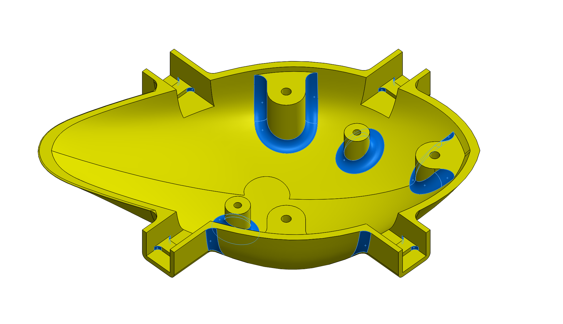
A third design aspect to notice is that every internal edge on this part, where two faces meet at an angle less than 180°, has a fillet added (see image above with fillets highlighted). Though unnecessary with 3D printing, this is absolutely critical when CNC is to be the final process, as this type of machining uses round tools that are unable to cut sharp corners.
Body Bottom

Materials:
Notable Features/Challenges:
- Organic geometry
- Battery pocket
- Weight reduction
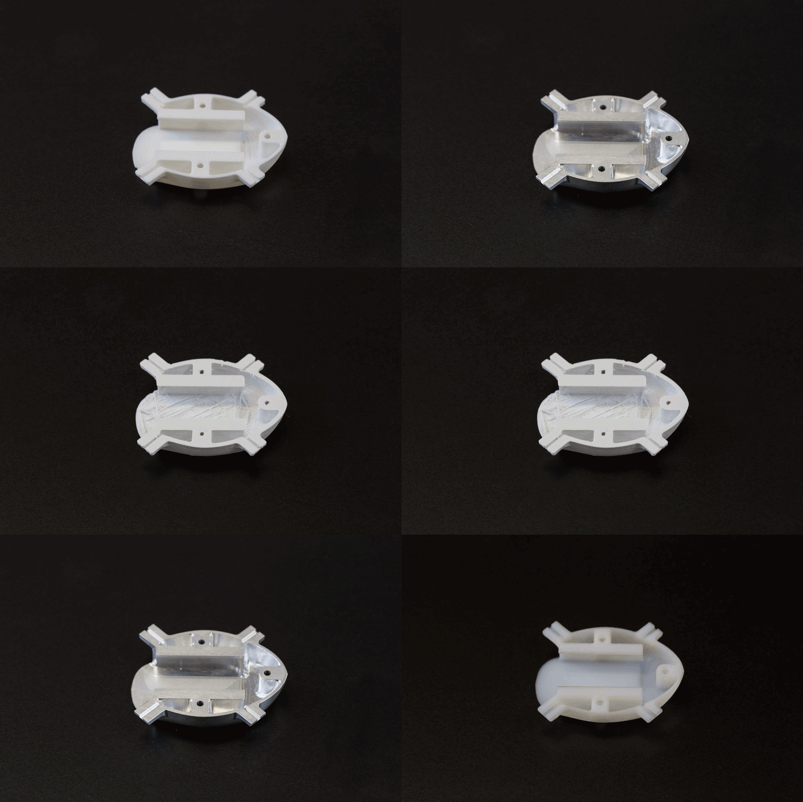
From the outside, the drone’s bottom half is quite similar to the top half. Again the design is organic, which 3DP processes tend to handle with few issues (other than visible build lines), but is usually expensive and time consuming to produce with CNC.
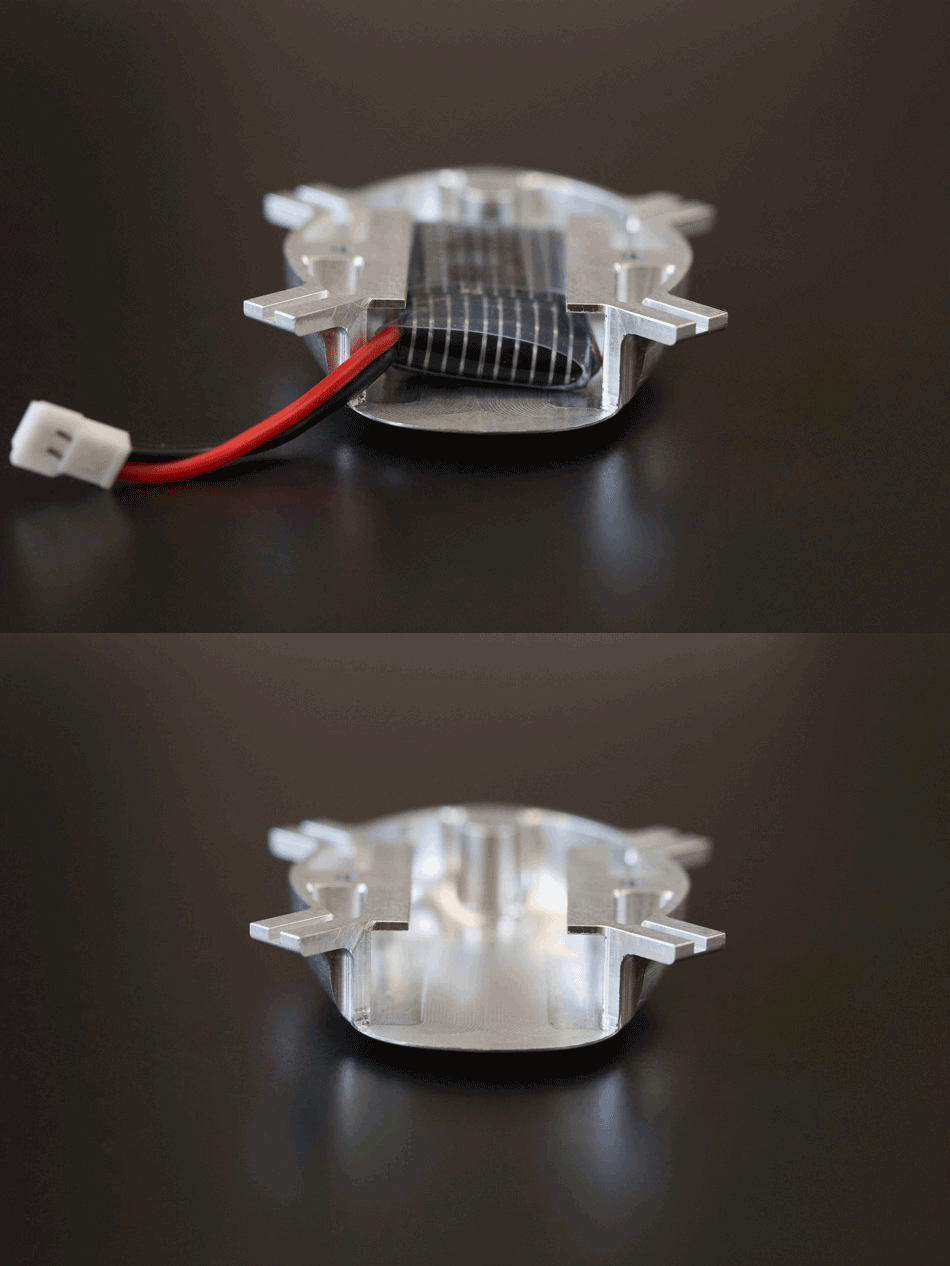
The most prominent area inside the bottom is the rectangular battery pocket. Instead of being a closed box, it is open to above, and an undercut ledge on either side helps constrain the battery vertically. This design eliminates the need for an extra set-up to machine the pocket from the side. While undercut features require a special CNC tool called a keyseat cutter, they are achievable, as long as the cut depth is not too extreme. Harvey Tool is a good resource for commonly available cutters, so you can make sure your design can be produced.
Around the battery pocket are several more pockets (again, filleted to account for CNC tooling) that follow the contours of the part’s shape. The only function here is for weight reduction, since this baby is destined to be airborne! If this was not a requirement, these pockets really only add complexity to the structure and should probably be left out.
Legs
Materials:
Notable Features/Challenges:
- Snap-fits
- Motor fit
- Overmolded foot (3DP only)
Moving away from the body, the legs were the next part we designed. These were created in a wide variety of printed materials but only machined in ABS, due to weight concerns of aluminum (doing everything in metal would have been far too heavy for the tiny motors).

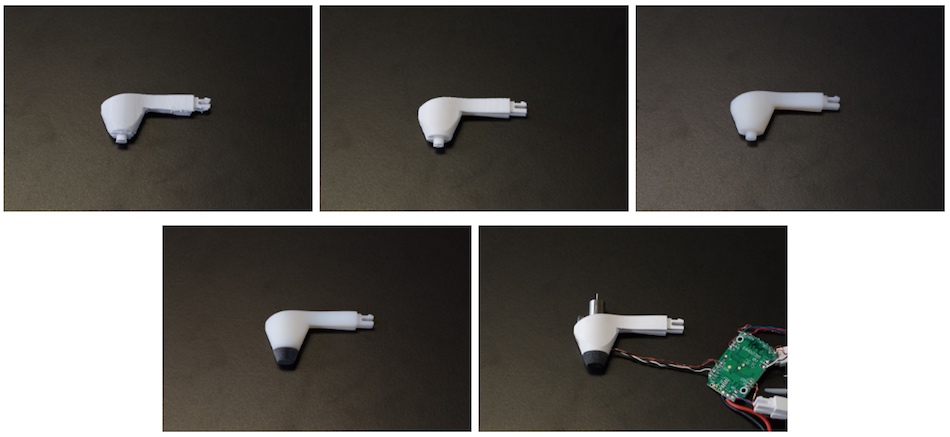
The most challenging feature on this part is the snap-fit tab, the geometry of which had to be carefully tweaked over several printed revisions (see above), to ensure a tight fit with the drone body before moving to CNC. If the fit was too tight, we’d risk tab fracture upon assembly.
Producing the motor pocket at the correct size was also somewhat tricky. 3D printed materials, even high resolution ones, tend to produce slightly undersized holes, so in CAD, they must be bigger than needed. Conversely, CNC can produce extremely precise features, so after the overall leg geometry was confirmed in VeroWhite, the motor pocket again had to be resized, to ensure it wouldn’t be too loose when the ABS plastic was cut.

A third fun feature that was only present in the printed version of this part was overmolding a Rubber-like foot onto the VeroWhite leg (in the CNC version, the foot was press fit over the leg). Multi-material prints like this are a great way to simulate multi-shot injection molded parts, without having to cut expensive tooling.
Propellers

Materials: VeroWhite
Aside from the harvested components, the propellers were the only part we didn’t directly design. We found an open-source model online and scaled it so that the prop would fit on the motor shaft. We printed these in VeroWhite only, to cut out CNC costs. Though simple, the thin twisting geometry of this part would be quite difficult to fixture and machine, without major benefits. In hindsight, ABS-like would have been a better option than VeroWhite for long-term durability (we’ve had several break during normal use).
Final assembly
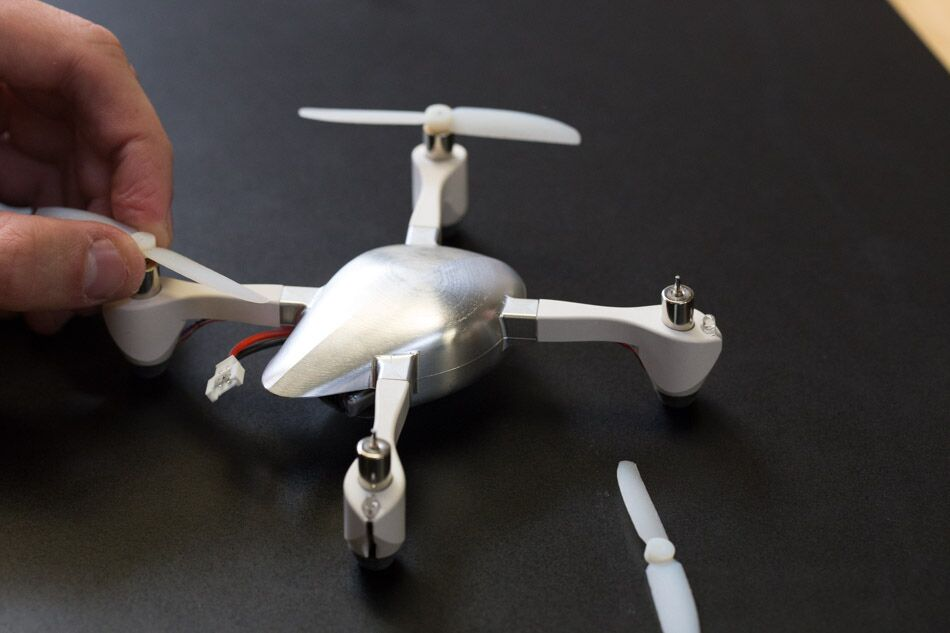
Once all parts had been refined to a satisfactory design point, and the CNC versions of the body and legs were cut, it was time to assemble everything! Most mating parts had already been test fit during the design phase, so assembly was a breeze (mostly).
All the electronic components fit inside the body without a hitch, as did the motors and LEDs in the legs. The holes in the propellers were slightly undersized, as planned, so they press fit smoothly onto the motor shafts. The biggest challenge was carefully routing the wiring from the legs through the channels underneath the snap-fit and into the body, then snapping the legs into place without pinching the wires. This took multiple sets of hands and would definitely be reconfigured in a future revision.With the drone assembled, the real question was, would it fly? The answer: Sort of.
The first test resulted in the Fictiv drone gliding across our test bench, more than actually flying. Everything was functioning, so why weren’t we airborne? There are likely a few contributors (more robust propellers would definitely help), but the easy answer is weight. Using electronic components sourced in a design than has been scaled up by roughly 20% from the original pushes everything to the limit of its operating capabilities. Add to that the fact that the body is aluminum, rather than plastic, and it seems surprising that there was any movement at all. Indeed, replacing the aluminum body with the machined ABS one resulted in slightly better performance—pretty darn good for a first fully assembled prototype, but still room for improvement.
Main Takeaways
Creating an entire product in a three-week sprint can be a stressful ordeal, but it’s also a hugely valuable learning process. In the world of design and engineering, your work will never end, if you don’t let it—there’s always one more design change to make or one more feature to tweak slightly. Having a time limit can be a good thing for your sanity, as it forces you to iterate quickly. This uncovers valuable insight about your design now, rather than later in the development cycle, when changes can be costly and more difficult to implement. In the case of our Fictiv drone, not only did we rapidly improve our design by moving through the different types of 3D printing and then transitioning to machined plastic and metal, but the prototypes we created in each step clearly showcase what each material is best at highlighting and testing. As we add more materials and processes to our platform, I hope to revisit this project. I can already visualize the introduction of many improvements and efficiencies by moving from machining to molding (hint: thinner walls), so stay tuned! In the meantime, check out the Fictiv Capabilities Guide to get the information you need for your own projects.


