It’s been a while since our last teardown here at Fictiv, so we knew when we came back that we had to take apart something really special. Something completely unique. Something…cool.
We present: the Coolest Cooler; the Kickstarter product that swept the nation in the summer of 2014, raising $13 million dollars from over 62,000 backers. The Coolest Cooler was developed by Ryan Grepper, in order to bring a multi-function cooler to outdoor events everywhere.
Each cooler includes a blender, a Bluetooth speaker, a USB charger, a knife, a bottle opener, a corkscrew, a center divider that can be used as a cutting board, and a few plates. The Coolest Cooler currently retails for $399.99.
The Coolest Cooler is an interesting consumer product, partly because of the problems the company ran into while trying to scale up production to meet overwhelming demand. Their initial delivery deadlines were pushed back a number of times, and some backers have reportedly still not received their orders.
Our coworkers were horrified when we told them that we were planning on ripping apart the cooler of the century. It does blend drinks well, so we understand their heartbreak. But we were too curious about why this cooler was so hard to manufacture to stop ourselves from breaking it down.
Here are the mechanical features of interest we’re drilling into for this teardown:
1. Assembly – rotational molding, expanding foam, and sub-assemblies
2. Design – complicated design that required many injection molded pieces
3. Mechanisms – two spring mechanisms and a blender

Assembly
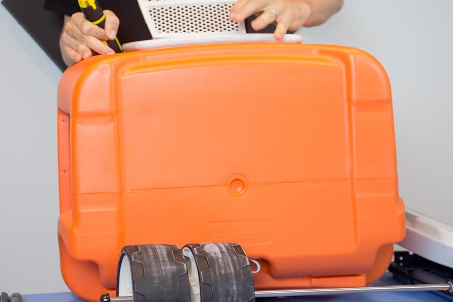
The main body of the cooler is made using rotational molding, a molding process in which a hollow mold is filled with plastic pellets, then rotated slowly in a heated chamber, so the plastic melts and covers the inside of the mold. Once cooled, the mold is opened, and the hollow final piece is removed. The orange outer body is rotationally molded into the color of choice.

Foam adhesive and a plastic structural lattice are placed into the outer body. Expanding foam is used as an adhesive and helps prevent heat transfer, keeping the cooler…cool. The inner body (white) is placed on top of the adhesive and lattice and left to cure together to create one large piece. The doors of the cooler are screwed into this main body. Most large hollow plastic parts are made this way—tooling costs are much lower for pieces of this size, compared to injection molding.
Theoretically, if injection molding was used for this part, an enormous block of steel would be needed to make each side of the tool, making the up-front material cost incredibly expensive. If you used injection molding, you’d also need to worry about the pressure required to hold a tool this large together, while pressurized plastic was shot through narrow channels. This is not a concern with rotational molding, in which plastic evenly coats the internal cavity of a tool using heat and gravity—no high pressure jets of plastic required.
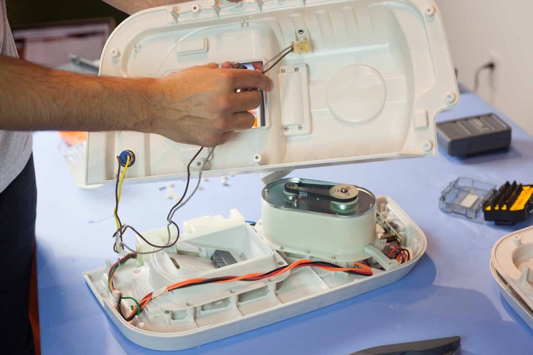
The Coolest Cooler’s appeal is that it has countless features built into one base—the cooler itself. But these features required their own sub-assemblies, in order to incorporate them into the main body of the cooler. In order for these features to be incorporated into the cooler, each has its own sub-assembly, which is incorporated into another, larger sub-assembly (like the doors of the cooler), which are then assembled into the larger cooler itself. Each of these sub-assemblies must have added up to increase the total assembly time required to make each cooler, which could limit the number of coolers that could be produced per day.
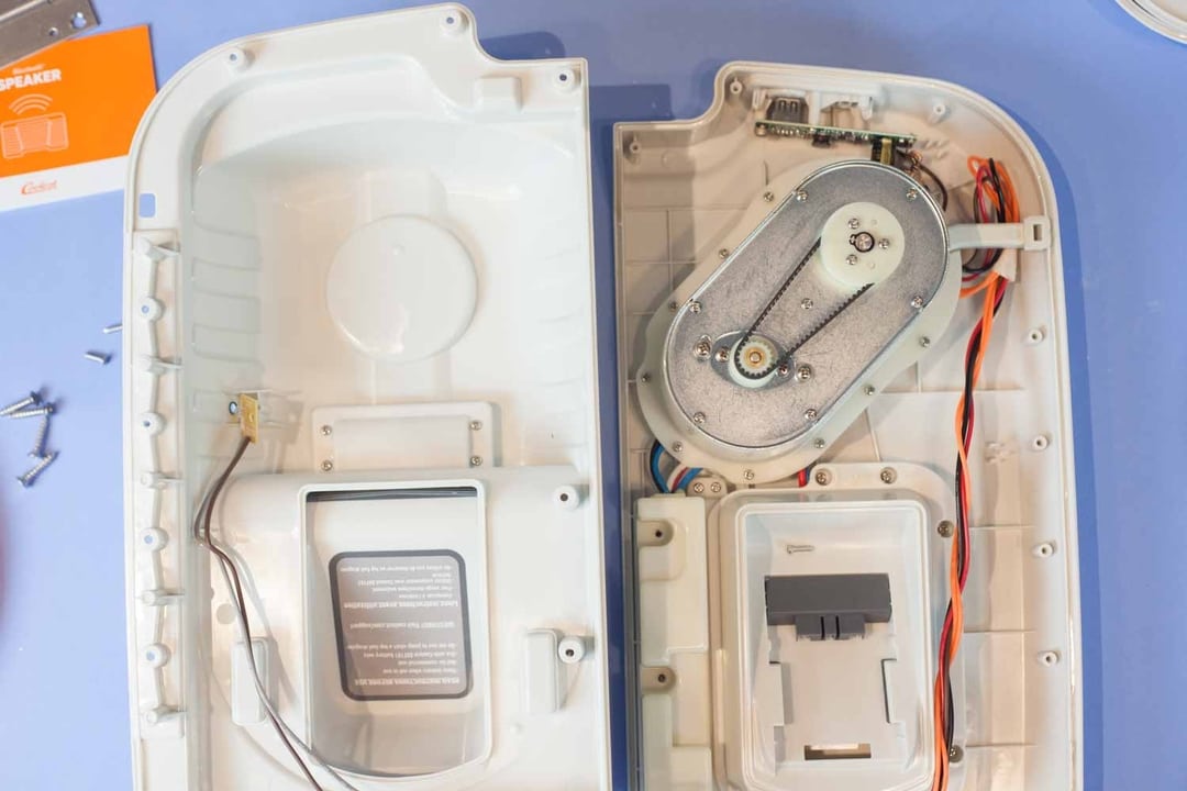
We noticed that the sub-assemblies we took apart were quite complicated, and required a number of injection molded plastic pieces in order to function. Specifically, we noticed a large number of parts required to create the holder for the speaker system. This over-complicated design was likely time-consuming and expensive. Let’s break it down in the next section.
Design
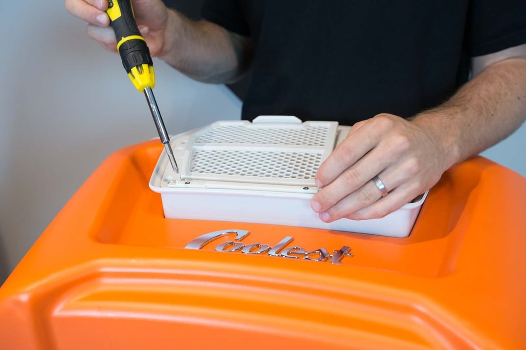
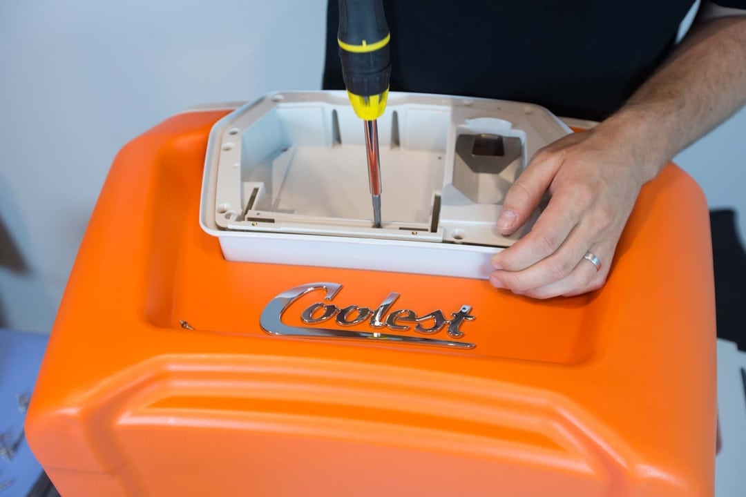
Large housing 1 attaches the entire assembly to the main body of the cooler. Large housing 2, attached to large housing 1, incorporates the bottle opener, which is embedded into the plastic. A smaller plastic piece, with helicoils pressed in, attaches both large housing pieces to the main grate, which holds the speaker inside the cooler, while still allowing sound to escape. Another plastic piece snaps over the edge to hide the assembly. All these pieces are for one sub-assembly—a rather complex design for a simple speaker holder/bottle opener. For this one sub-assembly, at least 4 injection molding tools had to be created. The designers didn’t leverage snap fits or quicker assembly options in the design.
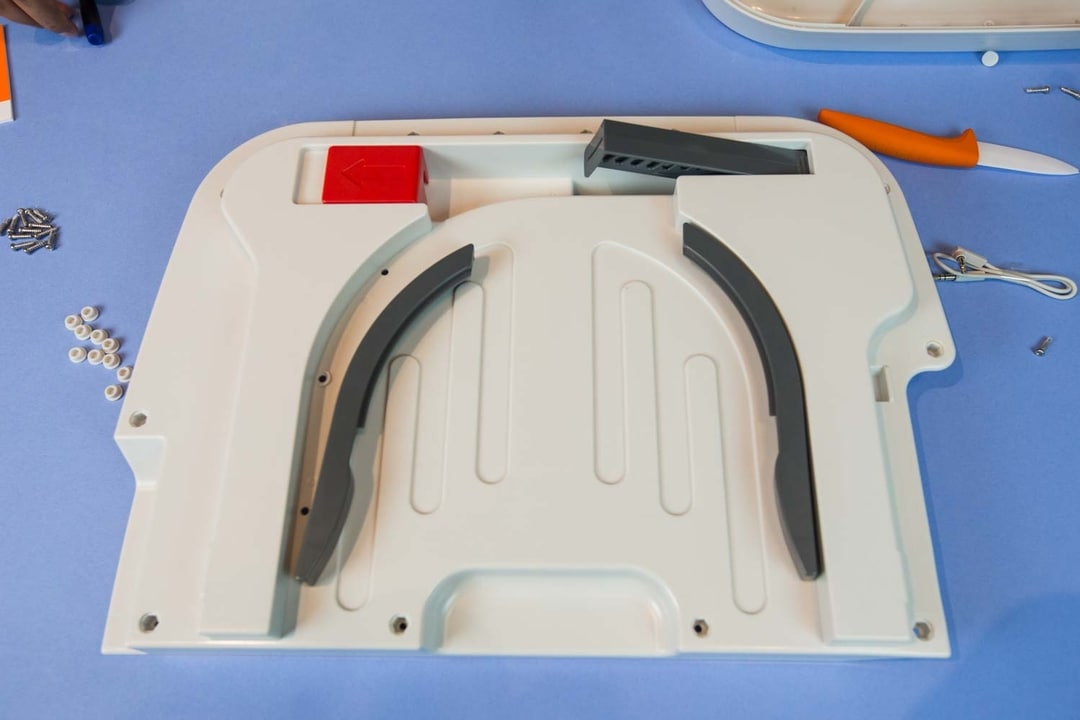
The door that holds the plates and knife also has a complex design. Two large outer housings are held together using screws. Two grey plastic pieces screw into the outer housings to hold the plates in place. A red plastic piece and a grey plastic piece hold the knife. There’s also a housing for the knife assembly. That’s about 5 separate injection molded tools! The takeaway here is that the cooler’s complex design requires specialty parts, which require injection molding tools, which increases the time and money needed to create the cooler.
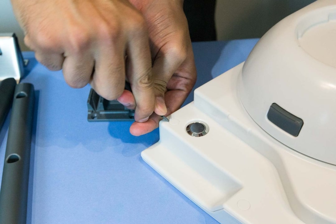
The cooler’s complex sub-assemblies are held together using self-threading screws, which bite directly into the plastic and are then hidden by plastic caps pressed into the housings.
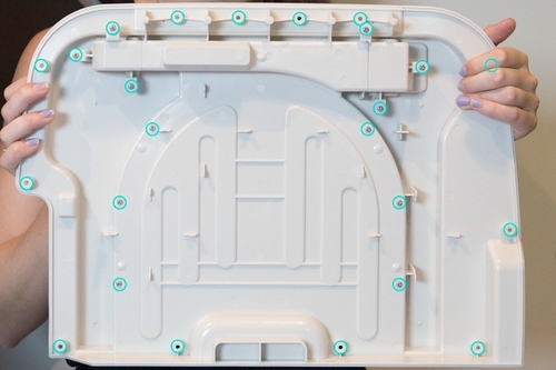
For example, on the door that holds the knife and the plates, 3 screws attach each plate holder to one side of the door, 12 screws attach the outer housings to each other, 4 screws attach the door to a hinge that is attached to the main body of the cooler, and 6 screws attach the knife housing to the main door body. Bonus: 8 plastic caps are pushed in to hide the outer screws from the user. These parts all had to be assembled by hand—each screw put into place manually, which likely increased assembly time and price per assembly.
Mechanisms
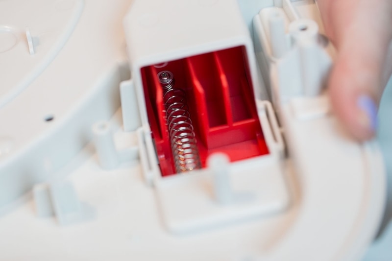
The knife is held in place on one of the doors of the cooler using two spring mechanisms attached to separate plastic parts. A linear spring is used to create a press release, and a torsional spring is used to prop up the knife holder, once the release is pressed.
On the same door of as the knife, the plates are held in place using two more plastic pieces that are screwed into the top-door of the cooler. The plastic pieces themselves are only slightly shorter than the height of the plates. This allows the plastic plates to slide into the small channel created by the grey pieces and the main door body, but be held firmly inside when the door itself is turned upside down as the cooler is packed up.
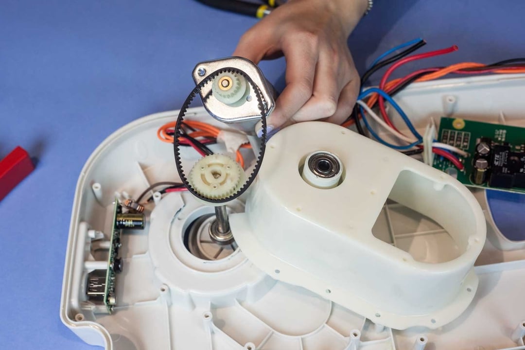
A spring mechanism is used to turn the blender on and off, connecting the battery to the motor when it is depressed. The motor turns a small gear, which is attached to a larger gear via a belt drive. This increases torque. This driven gear is press-fit onto one end of a shaft, while the other end is connected to the large plastic piece used to spin the blades of the blender. The shaft is then press-fit into a bearing that holds the shaft steady as it spins the blades of the blender.
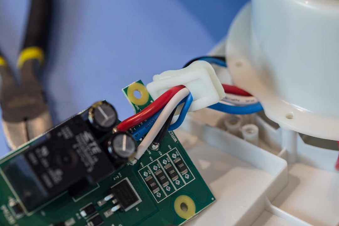
The PCB that controls the blender is held in a watertight enclosure. Small elastomer pieces ensure that the wires can enter the PCB enclosure, while keeping any water out.
Main Takeaways
The Coolest Cooler is a great outdoor adventure accessory. The blender was surprisingly effective, and the speaker provided some great music for us as we tore down the main body of the cooler. I still mourn the loss of the cooler and want one of my own to use this summer.
While I personally loved the use cases of the cooler, its manufacturing couldn’t have been easy. Often, a designer’s choice is between easy design for manufacturing or easy design for assembly. (Complex parts that do multiple things make assembly much easier, but increase upfront tooling cost, while simple parts make machining and tooling less expensive, but increase assembly time.) Obviously, the above example isn’t always true, as our teardown shows.
The number of specialty injection molded parts must have made up-front tooling costs extremely expensive and must also have increased lead time as the tools were cut. And the number of individual features and sub-assemblies needed to add in the things that made the cooler “cool” increased the assembly needed to create the final product.
Overall, the main driver for lead time and price would be those small features that really set the cooler apart from its competitors. The blender, for example, added a complex electronics component that required a specialty housing to ensure the pcb wouldn’t get wet. The main body was made using the same process numerous other coolers use and didn’t redefine what it means to be a cooler—the accessories that came with the Coolest Cooler took care of that.
If the designers had slightly more time to design the “coolest” individual features into the main body of the cooler, it might have decreased up-front cost and assembly time. Decreasing the number of parts in each sub-assembly (like consolidating the speaker housing into 3 parts, instead of 5) would lower up-front costs for tooling and limit the amount of assembly needed for the cooler.
The makers of the Coolest Cooler were crunched for time when bring this product to market, which limited the amount of time they could spend streamlining their design. But this is a great lesson for designers everywhere to learn—limiting individual, complex parts and necessary assembly will make your designs…cooler.


