By now, you’ve almost certainly seen a hoverboard out in the wild. While the current models still aren’t quite the quality of Marty McFly’s hoverboard (thanks, Doc!), it’s just as mesmerizing to see someone majestically gliding through the daily San Francisco sidewalk traffic. Not everyone feels the way I do, though—some find them dangerous (like the government…) or consider them a nuisance. I think we can all agree that the hoverboard is the most polarizing consumer product in recent history—you either love it, or you hate it.
For an engineer, hoverboard construction and wiring is intriguing. Factories and small mom and pop shops all over China are replicating and selling hoverboards that range from $200 to $2,000. Companies are suing each other over patents and stolen IP. Battery and electrical issues are being found that have caused tragic fires.
Needless to say, we at Fictiv couldn’t wait to dig in and after tearing down a hoverboard, it’s easy to see why this is one of the most replicated products on the market.
Let’s take a look!
Ready to start building your own awesome project? Visit Fictiv for 24 hour turnaround on 3D printed parts.
The Enclosures

Looking at the hoverboard, you can see that assembly is done with the top side facing down. We flip it over, where there are 16 screws holding the bottom cover onto the rest of the assembly.

The bottom pulls off easily enough, after disconnecting some wire harnesses from the internal boards and battery.
The bottom covers themselves are pretty simple injection molded ABS pieces; the plastic is white, and the red-color is applied with spray paint (you can see the two white spots where there is no paint coverage). These hoverboards come in many colors, so painting the covers (rather than doing colors in-mold) is a much more economical way to deal with unpredictable color demand.

You can see a panel-mounted light and button attached to the bottom cover. These are usually used for industrial equipment control panels and they’re cheap and widely available.

The “turn signal” light board and cover are mounted to the bottom panel. Eight LEDs each—that’s bright!
It’s interesting to note that the PCBA was just glued into the light cover. The light covers themselves were screwed and mounted into the bottom panel, though.

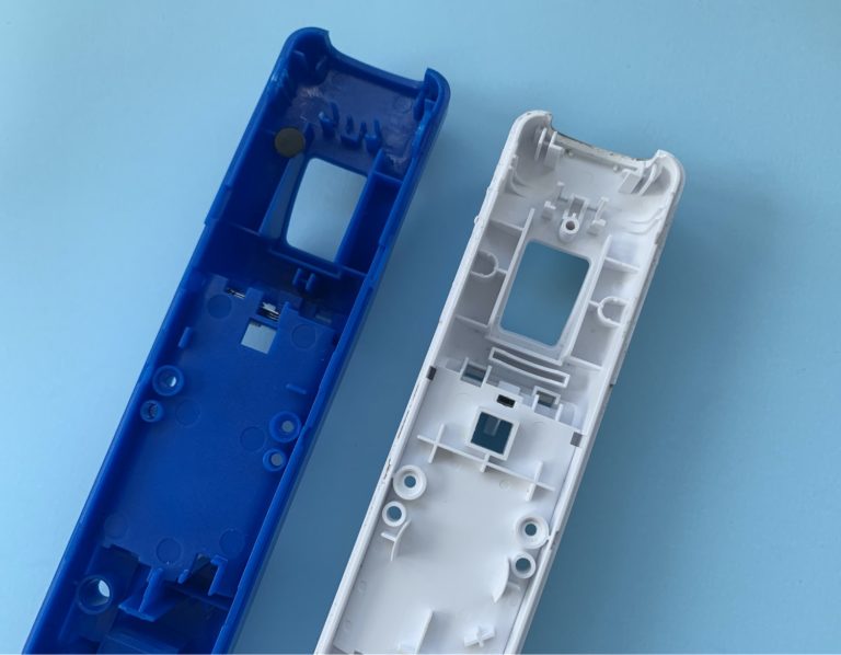
Here are the top covers—they’re also simple injection molded ABS pieces.
To light up the power and battery signals on the board, the manufacturer placed an LED circuit board behind cutouts in the plastic cover, then used stickers to mask the shape of the light. To hide the stickers, they covered the areas with tinted polycarbonate windows that pop off easily. The results are actually pretty great—we didn’t notice the stickers at all while playing with the hoverboard.

Below are the LED boards—we’re actually surprised they’re not the same.

The Electronics
The top half of the assembly looks more complex, but if you follow along, you’ll see it’s really quite simple.
You have a main PCBA, two gyro PCBAs (identical), and a large lithium-ion battery pack. It’s interesting to note here that there still isn’t a motor to be seen, making us think there are actually two motors embedded in the wheels.

After removing the gyro boards and the main PCBA, we’re left with a battery (being held in by a plastic bracket), two metal plates screwed down to hold the wheel shafts, and four rubber triggers that are depressed when a rider stands on the rubber pads on the hoverboard.
If you look at the aluminum plate on the left, that’s where the main PCBA was located. There were fourteen screws and washers holding down the board, which was probably done to reduce vibration on the critical components.

A few more screws and little arm strength leave us with:
- Four injection molded ABS enclosure pieces
- Four injection molded polycarbonate light covers
- Three plastic brackets
- Two gyro PCBAs
- Four LED PCBAs
- One main PCBA
- Two wheel assemblies
- One battery pack
- This two-piece casted cnc aluminum chassis
Plus some odds and ends. Seriously… that’s it!

What makes this product amazing is that it combines several simple mechanisms that work together to solve a complex problem.
The Mechanisms
Infrared Sensor

As previously mentioned, the rider stands on a rubber pad on the top side of the hoverboard. Internally, when the rubber pad is depressed, it interrupts an IR sensor pair, which tells the motor on its side to move.
When all the IR sensors pairs are interrupted, the hoverboard stands still. When someone leans forward or only breaks the front IR sensors, the hoverboard is told to move forward. Or, if the person’s right foot leans forward, while his or her left foot leans backwards, the front right and back left IR sensors are broken, so the hoverboard rotates counter-clockwise.
Chassis Rotation

The chassis rotates around a simple steel bearing shaft that connects the left and right sides of the hoverboard. The steel shaft is also hollowed and used to pass electrical wiring from one side to the other. A rotational limit is added by using a curved slot opening on one side of the hoverboard with a shaft on the other half that glides within that opening.
The Wheels (Motor)
As we expected after opening the body, the motors are located within each wheel, and they’re heavy! Each wheel weighs about twelve pounds. The motor is a three-phase AC, permanent-magnet brushless motor.
We know it’s three-phase AC because there are three thick wires coming out of the shaft, in addition to a five-wire harness going to the motor controller.
On a battery-powered device, you normally only see DC components. However, in a system that requires high power, AC motors are more efficient. AC motors also have more control over their start-up torque than DC motors, making the hoverboards just slightly less terrifying.

Initially, it looks like a pretty well-built motor, until you realize that the manufacturer used bamboo sticks as spacers between the coil windings and their slots—looks like a hack to us. These bamboo sticks are commonly used for BBQ meat skewers ubiquitously found at Chinese night markets.
Using spacers to stabilize the coils and keeping them compact against the armature core is a common practice in motor manufacturing. Maybe it’s actually kind of ingenious that the manufacturers used off-the-shelf components (from an unrelated industry) to achieve this goal?
Looking even closer, you’ll also see thin sheets of white plastic wrapped around the coils. These act as insulating liners.

BOM of Major Cost Drivers
Hoverboard major component BOM:
- One main PCBA
- Two motor wheels
- Two gyro PCBAs
- One Lithium Ion battery pack
- Cast aluminum internal chassis
- Injection-molded plastic housing
Looking at the BOM shows just how simple this product is and why manufacturers in China are able to replicate and manufacture it so easily. What looks on the outside like a new, cutting-edge technology product is really just a couple of sensors and motors. There is a lot of space inside the enclosures, so the manufacturers can use lots of off-the-shelf components, without spending time and money on miniaturization.
The IR sensors tell the wheels which way to spin and the gyro measures the tilt and tells the wheels how fast they need to spin to keep the person upright.
The assembly is simple and clean—no fixtures are really needed, except maybe a holding fixture to steady the oddly shaped hoverboard upside down during assembly. All wires are connectorized, making the product easy to rework and repair.
After tearing this particular hoverboard apart, we feel like we got a pretty well-built one. We even charged this thing three times without it catching on fire; although, for the first charges, we took the extra precaution of charging it in the bathtub.
The best part of this teardown is that we can actually put it back together! You’ll catch me at the local skatepark. Peace!