Big thanks to Dyson for reviewing this teardown.
By the Numbers:
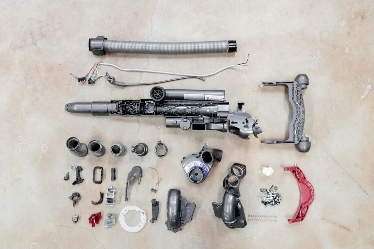
- 167 parts
- 74 fasteners
- 7 types of plastics
- 1 PCB
- 2 mechanical switches
We’ve long been fans of the innovative work of Dyson. Their products are immensely creative, beautifully designed, and mechanically impressive. And on top of that, we love Dyson’s transparency and willingness to share just how their products are made.
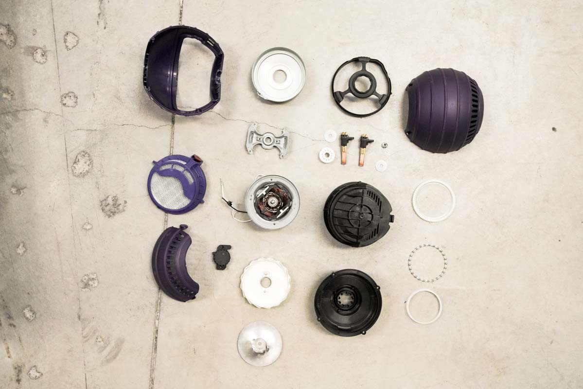
So we got our hands on one of the classic Dyson Ball Vacuums to venture inside and see for ourselves the mechanics that make up one of their flagship products.
There are 5 main systems that make up this awesome vacuum cleaner:
- Motor
- Vacuum Head
- Cyclone
- Handle
- Tube/body
We’re going to take a look at each of these systems to investigate the inner-workings of Dyson’s technological innovation. Onward!
1. Motor
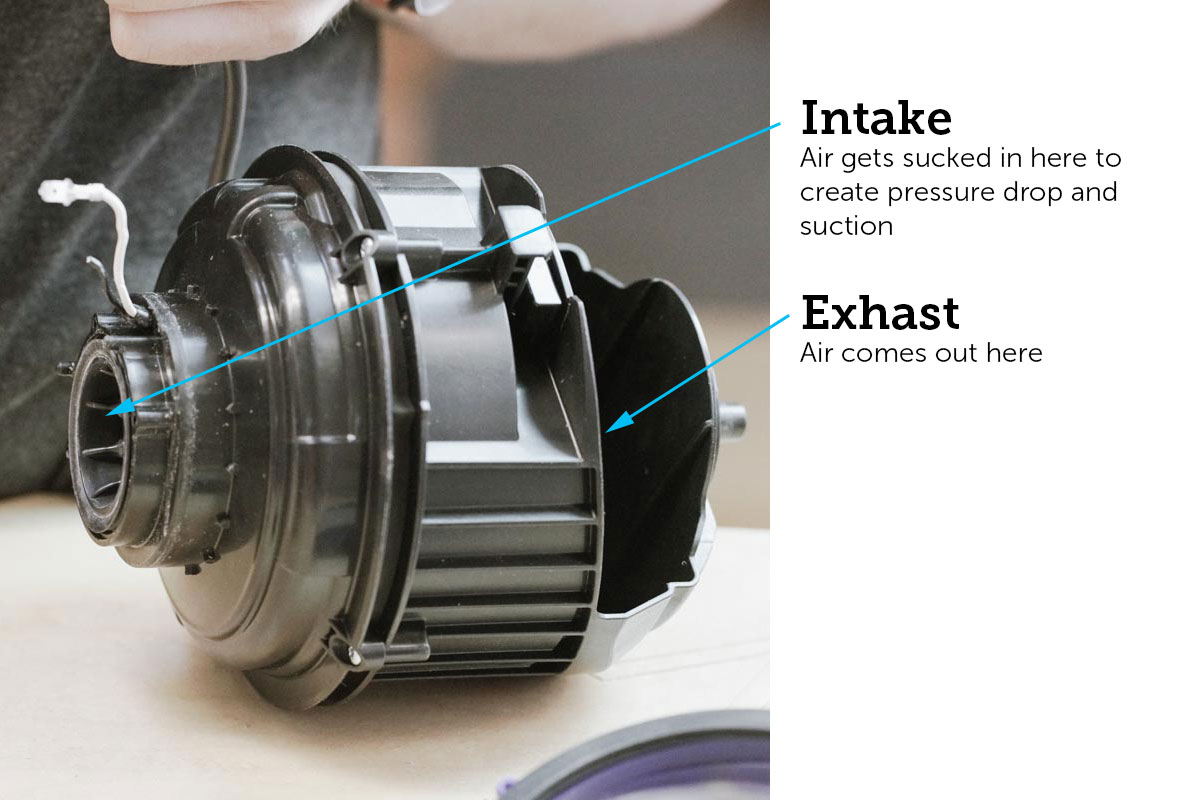
The motor is the heart of the vacuum cleaner and is the main instrument of the impressive pressure drop and suction that Dyson delivers.
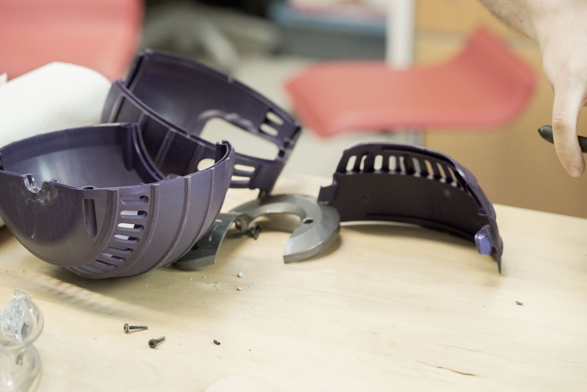
The motor is encased in the classic purple ball as the housing unit, made of GFPP (glass-filled polypropylene). It’s interesting, and ingenious, that they placed the motor in the center of the wheel to maximize space and create a very low center of gravity.
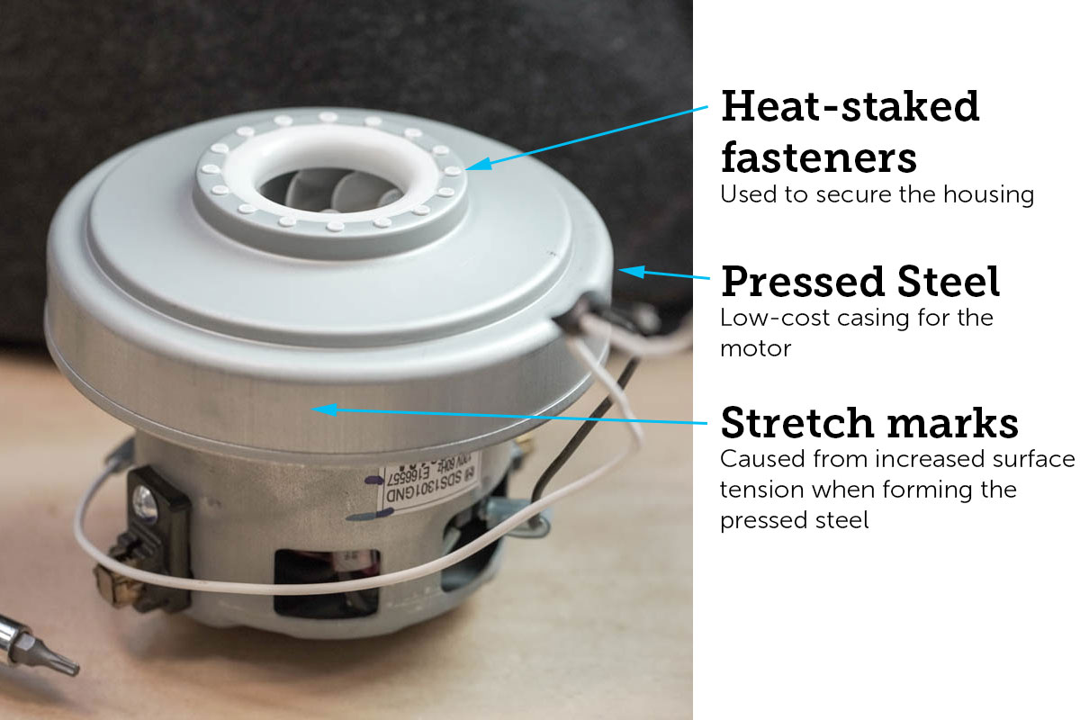
After removing the main motor housing we’re presented with the pressed steel casing and the motor itself.
You can see the stretch marks here, which are caused from increased surface tension when forming the pressed steel.
You can also see the heat stakes around the top ring. A single heat pad would have been used to stake all of the plastic fasteners on the top to secure the housing, which definitely saves on assembly costs.
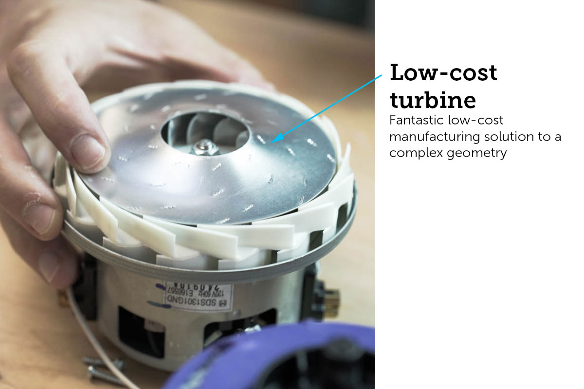
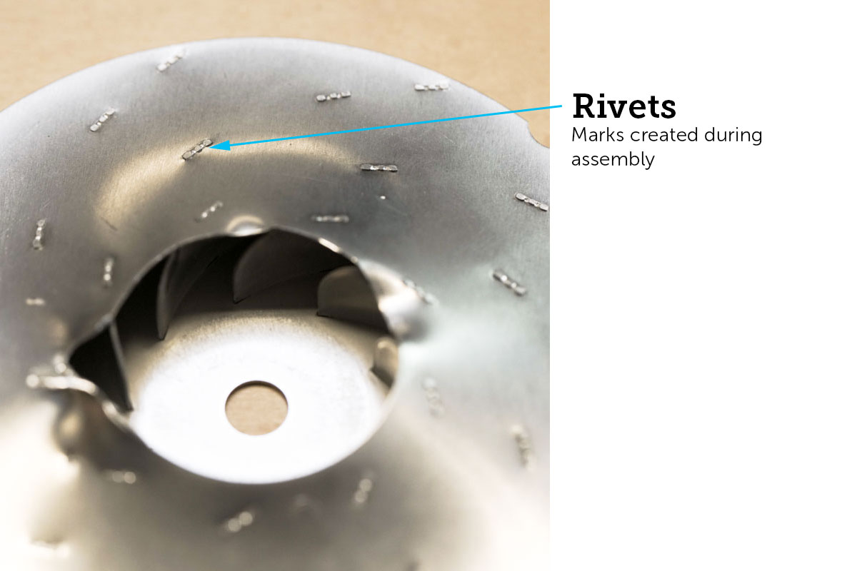
The turbine, which creates the pressure drop in the air, is a fantastic low-cost manufacturing solution to a very complex geometry. Here the 3D turbine is broken into 3 different 2D shapes which are stamped and then assembled. The marks on the top are the rivets from assembly.
2. Vacuum Head
The vacuum head is a belt-driven system, great for linear motion transfers and very efficient, usually achieving around 98% efficiency.
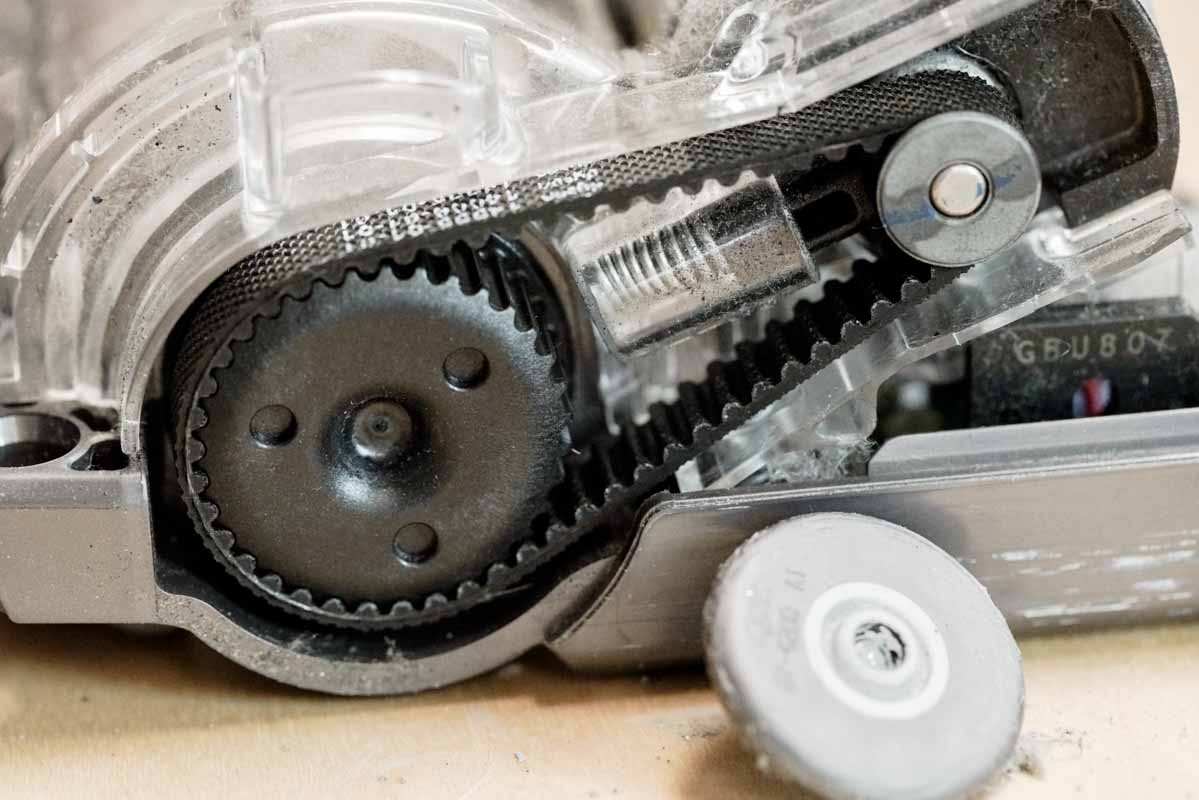
Compare that to a worm gear, which can fall in the 50-60% efficiency range depending on the ratio.
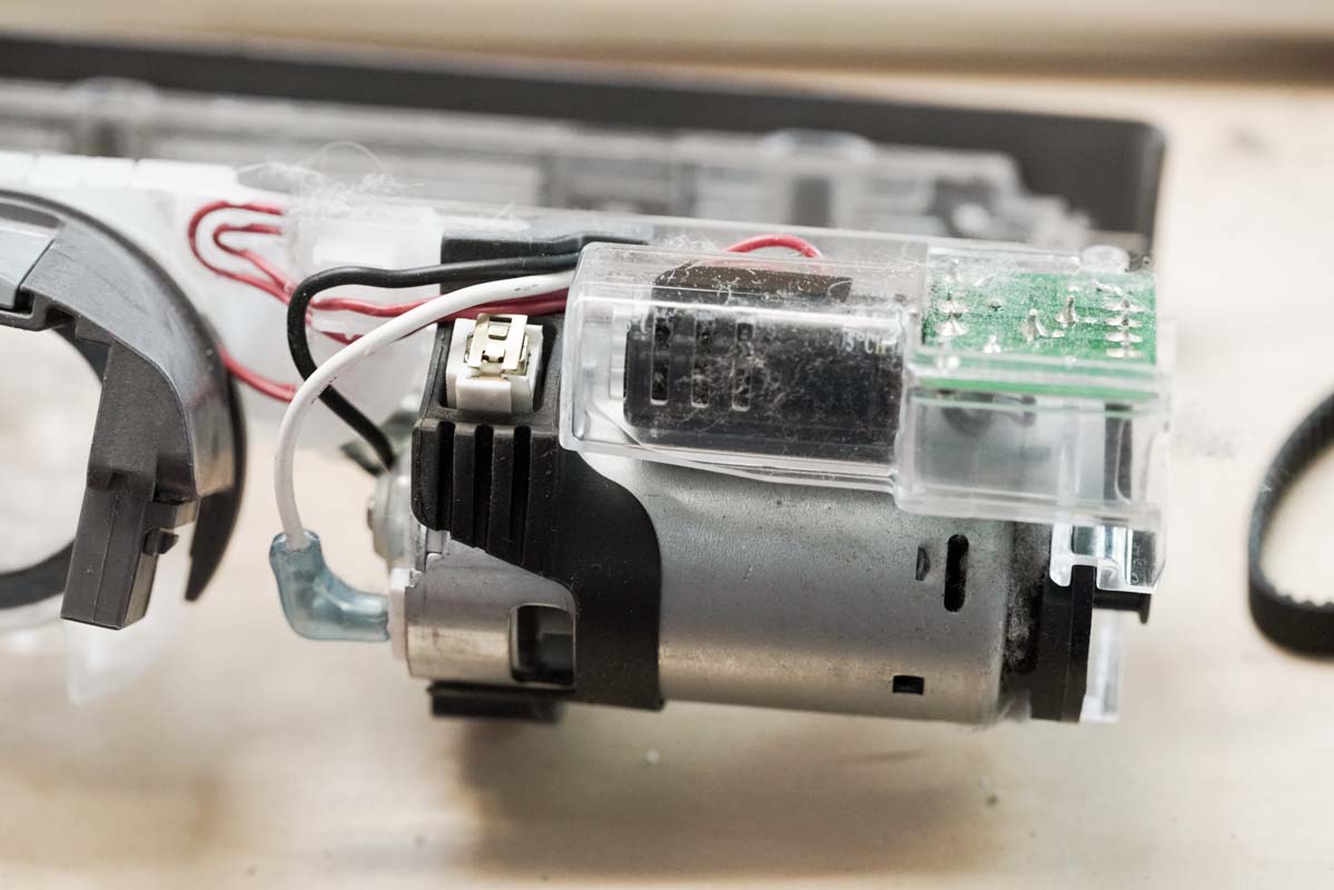
The PCB in the vacuum head is the only one we found in the entire vacuum cleaner and guessing by the very large capacitor, we’d say it’s used to step down the voltage and current supplied to the smaller motor.
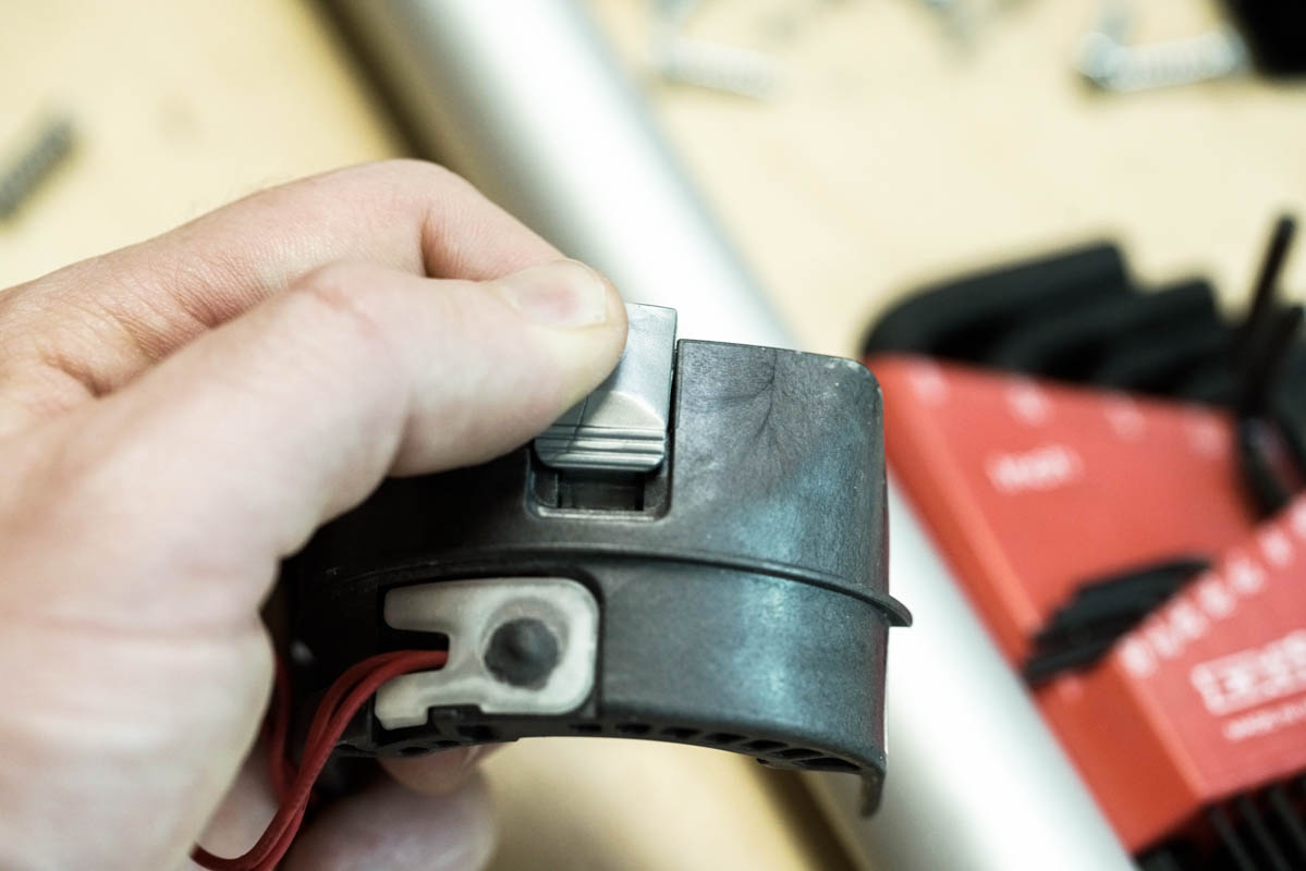
This nifty switch isn’t a major player, but we love mechanisms and this one that releases the motor is pretty cool so we couldn’t help but point it out. If you’re interested in how it works, send us a note. 🙂
3. Cyclone
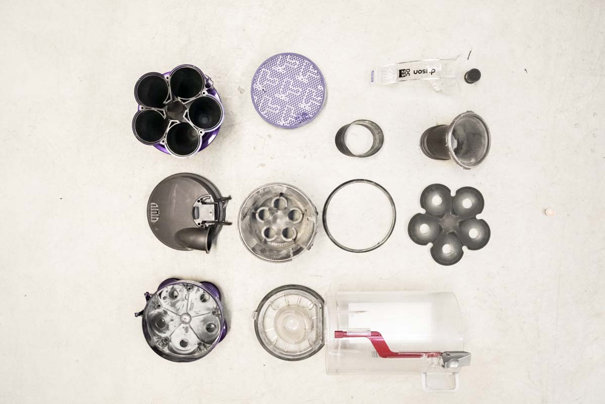
The cyclone is the true invention in this product and what Dyson is known for. The cyclone is all about filtering the dust and dirt from the airflow of the machine. At a basic level, the principal works through the addition of mass by increasing the acting G-force through increased acceleration. Yep, that’s the basic level.
And because this is so cool, let’s geek out a bit to explain the physics further. Quick physics 101 recap: A1 * v2 = A2 * v2, where A is the cross-section area and v is the velocity. So as the cross-section area decreases, the velocity increases creating more kinetic energy. Due to good ol’ conversion of energy, as the energy increases the pressure must decrease in parallel since pressure is really just energy density (P = energy / volume). And if you really want to geek out, ask us to explain Bernoulli’s equation and laminar flow!
Pheww, that was fun! 10 points for everyone still with us.
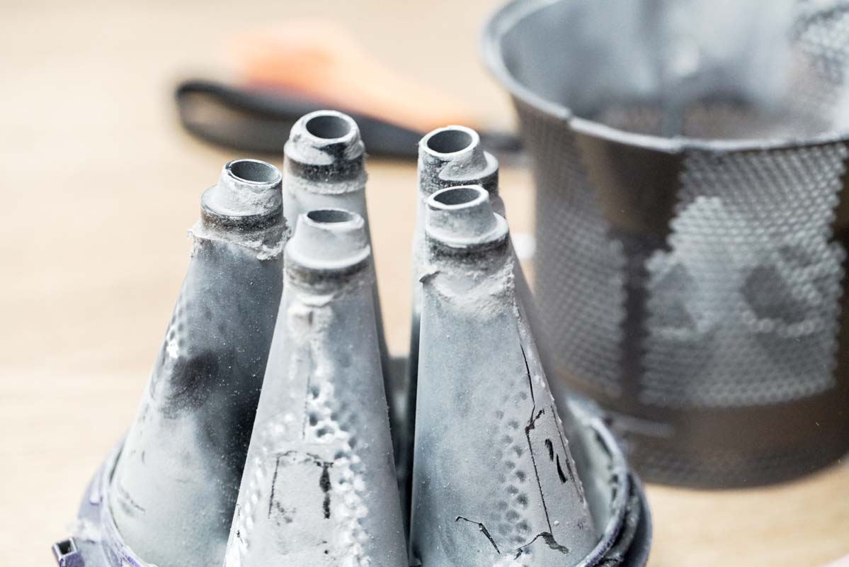
Nozzles! These guys make for some awesome suctions.
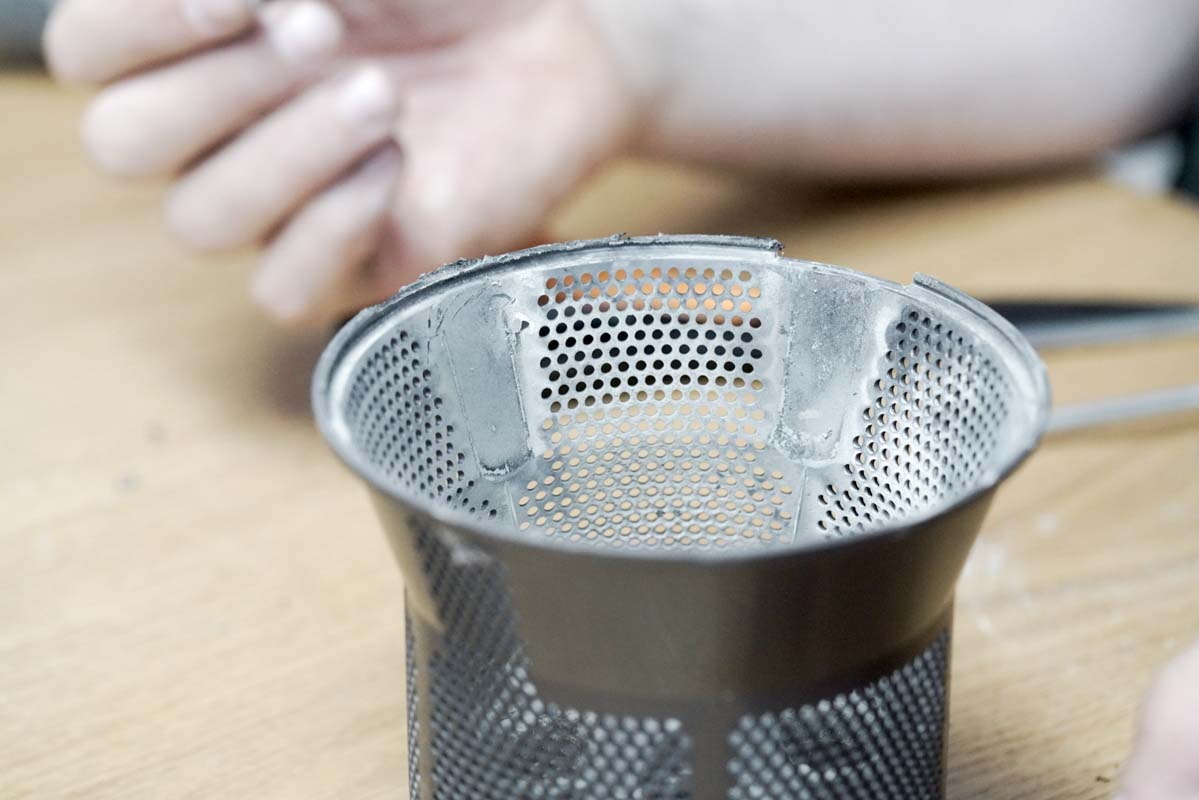
Here’s an impressive 2-part molded piece with 6 actions to create the mesh. We guessed that the small holes were created using EDM (electric discharge machining), but Dyson confirmed that they were in fact molded using 2mm rods attached to a retracting action of the mold tool.
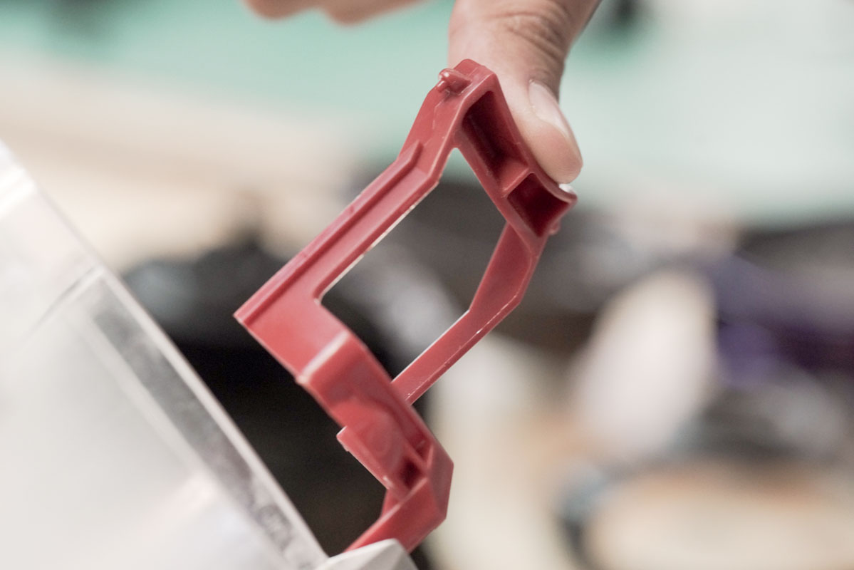
And following our love affair with mechanisms, here’s a simple push button used to release all the dust bunnies into the trash. Cool! We also love the different colors here that highlight the lever.
4. Handle
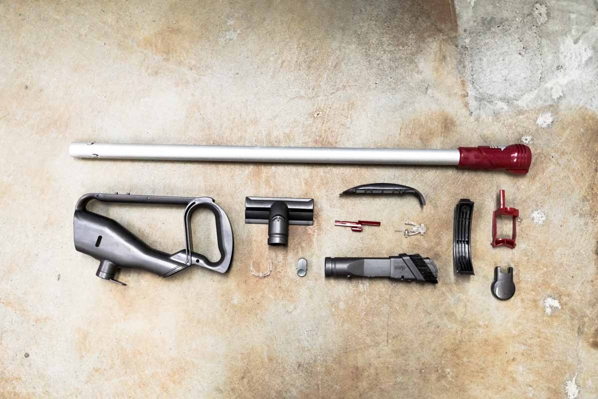
The handle is one of the simpler pieces on the vacuum, but is a terrific example of expert material use for cost savings. The main arm of the handle is made of extruded aluminum and then the rest of the pieces are different types of plastics. All the cosmetic plastics are ABS, the cheaper non-cosmetic plastics are PP (polypropylene) and the stronger plastics are GFPP (glass-filled polypropylene) and PC (polycarbonate).
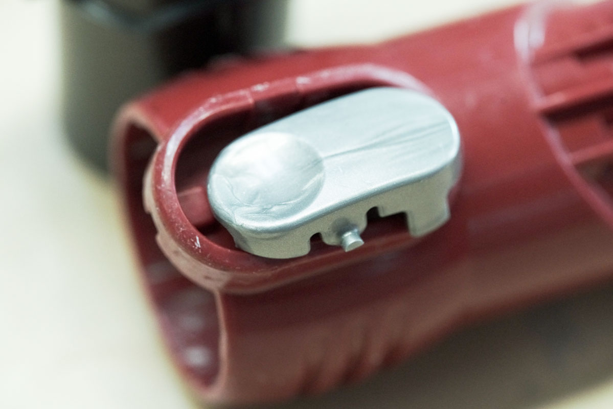
Above is also another great rocker mechanism for quick release of the attachment heads.
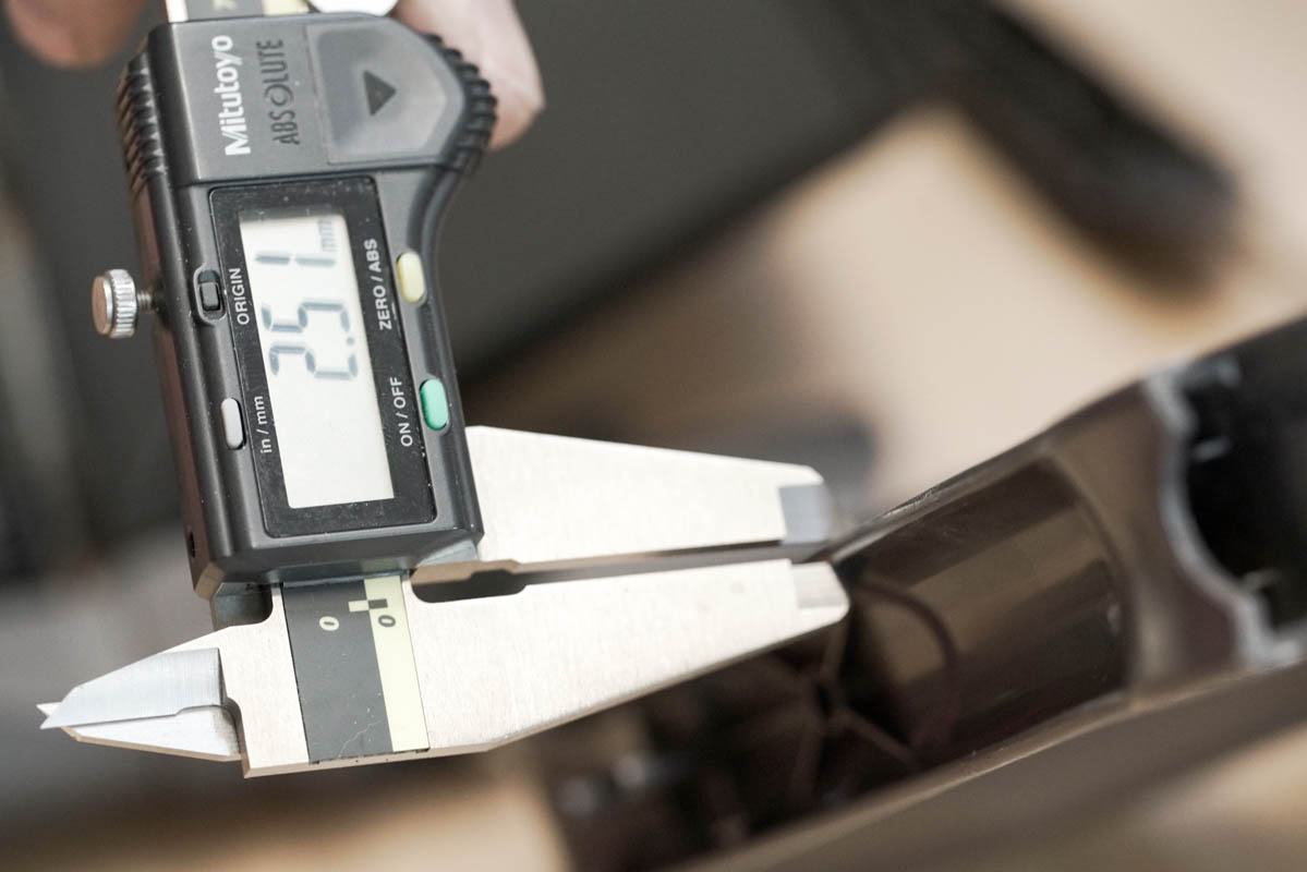
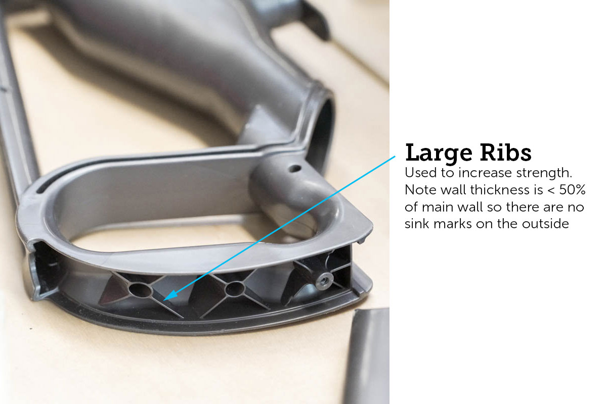
Throughout the plastic parts we see a standard 2.5mm wall thickness. Additionally, large ribs are used to increase the structural integrity of the ABS parts. Some places have sink marks due to these large ribs, but it appears to be a non-issue for Dyson.
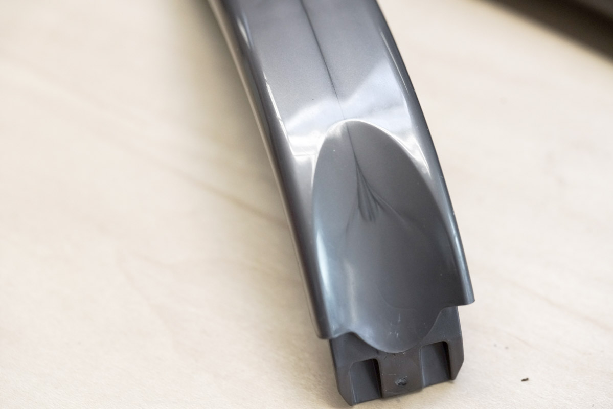
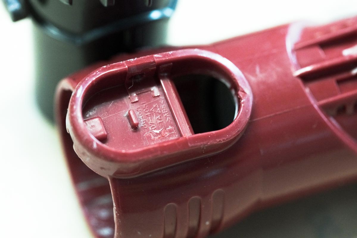
On the handle we can also see flow lines from the injection molding process, which occur due to small gates. This appears to also be a non-issue for Dyson though. In fact, it actually appears to be a part of their aesthetic. Interesting that their product is still considered so beautifully designed even with apparent sink marks and flow lines. It’s a brave new world, people!
5. Tube and Body
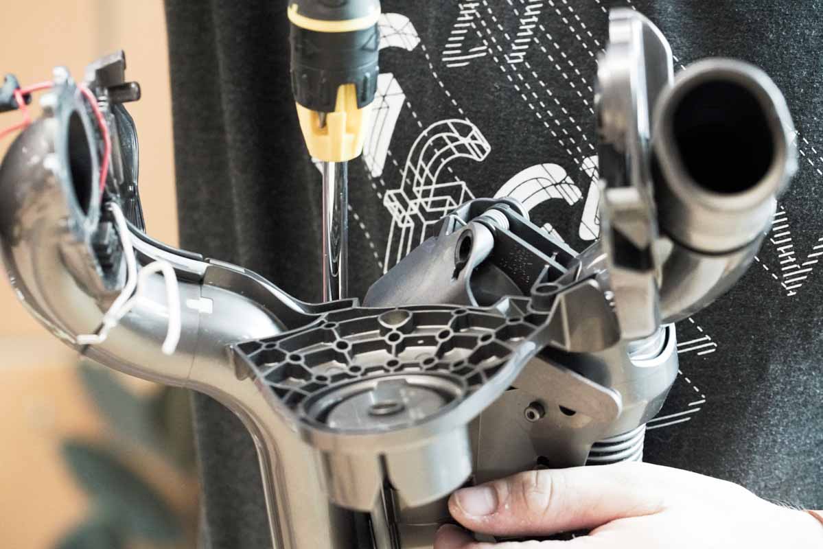
The main body has some very impressive injection molded parts. So much so that we had to take a dremel to the parts to figure out just how they made them!
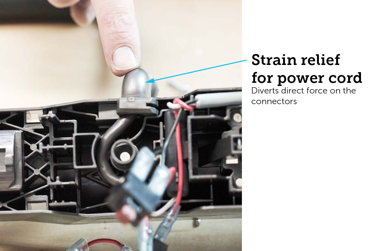
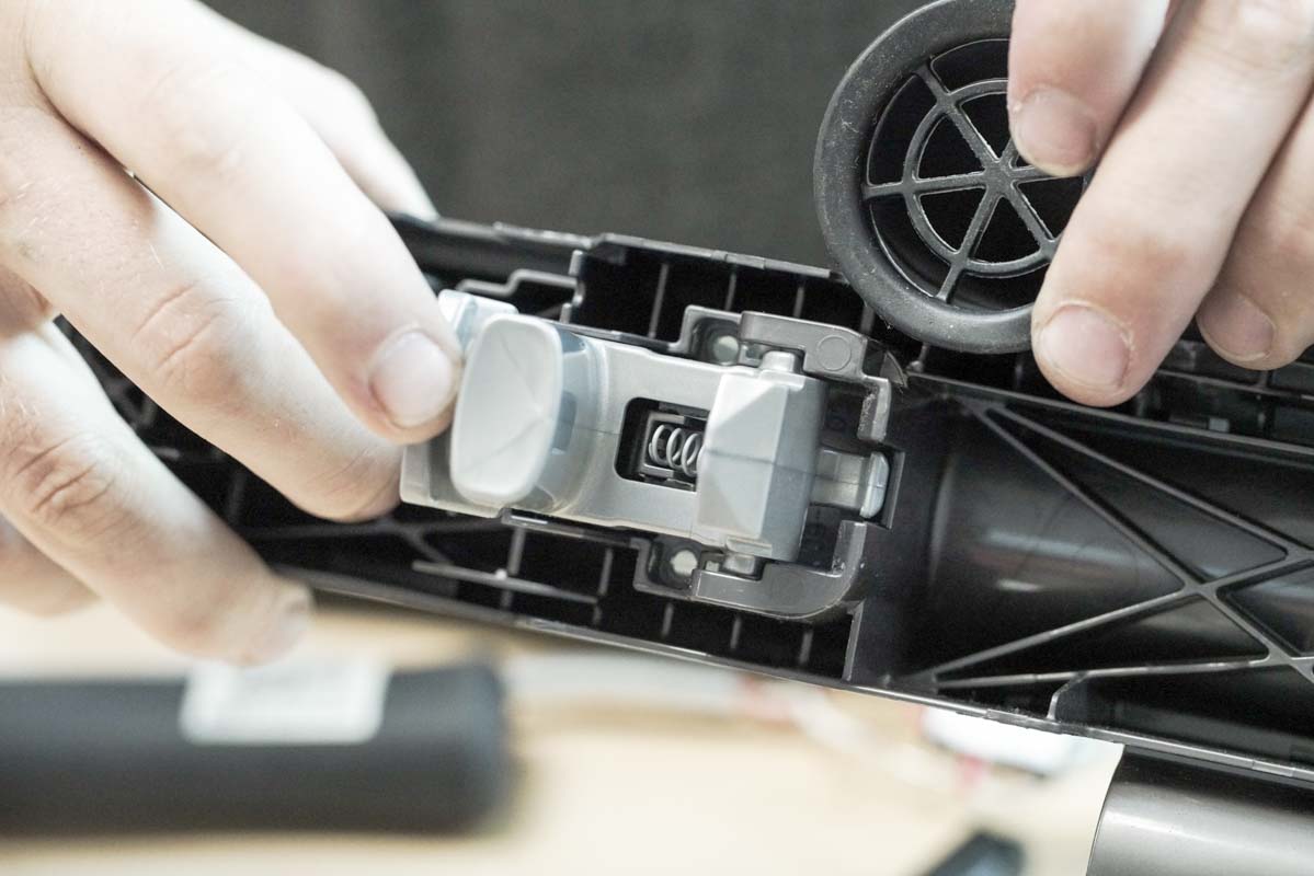
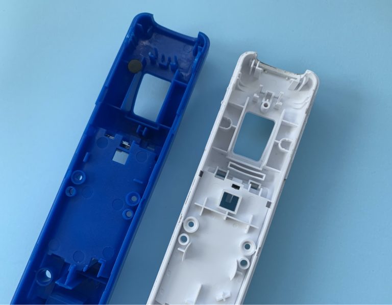
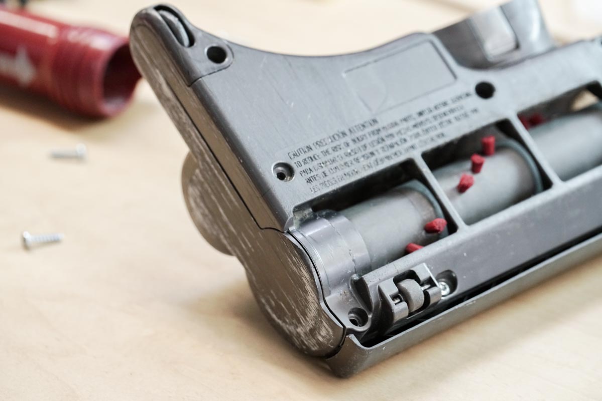
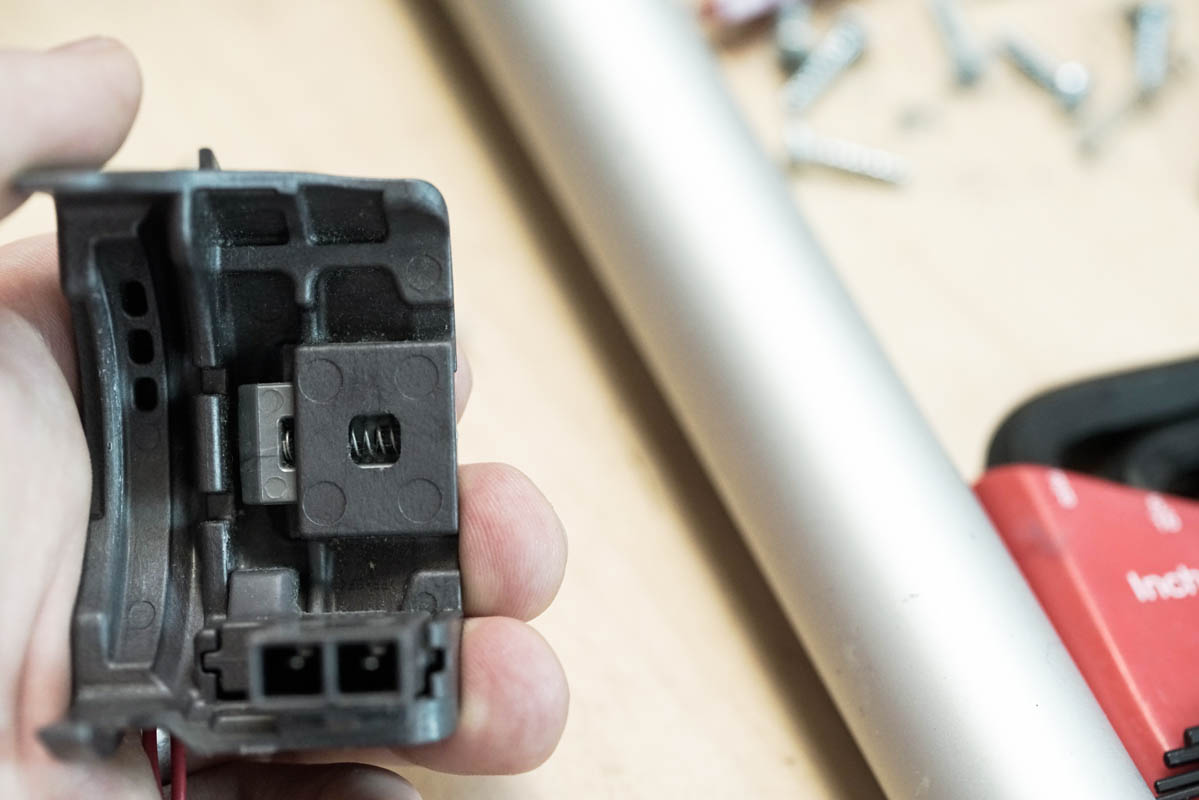
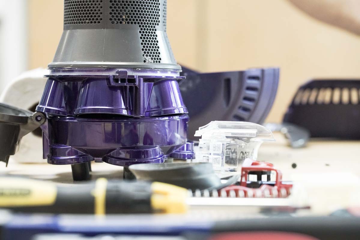
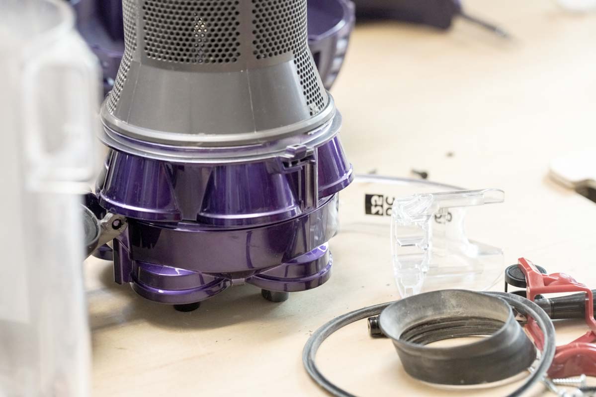
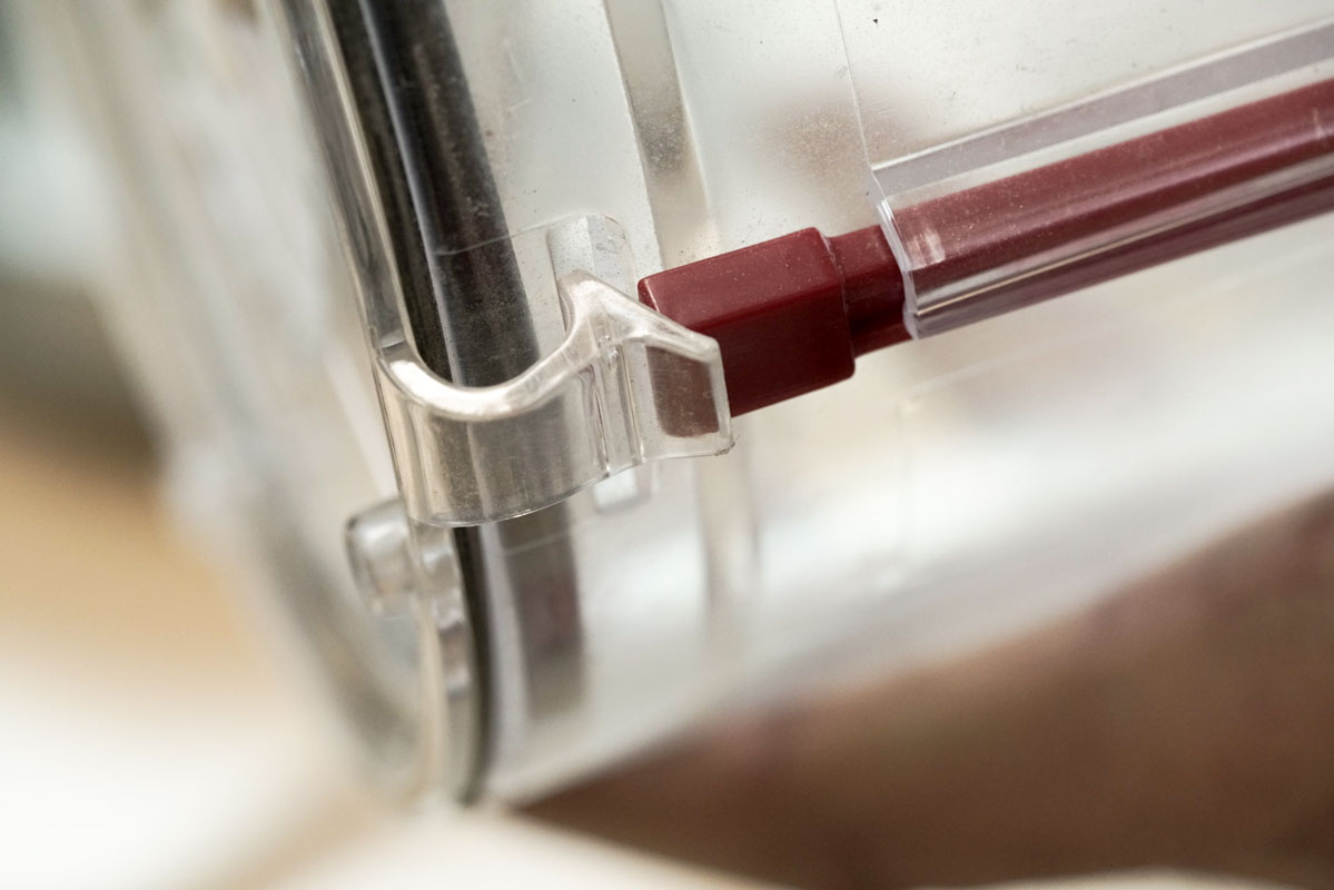
When we first open the body up, we’re presented with the only switches in the entire vacuum. In the photo above you can see where the power cord snakes through to the main electronics. Since people have a tendency to yank on the cord, it’s clear the Dyson team spent a lot of time creating a secure strain relief for the cord, diverting direct force on the connectors.
On the right, you can see our favorite latch mechanism on the vacuum which releases the cyclone. It’s a spring toggle mechanism that rocks to release the cyclone.
Side note: check out all the incredible toggle mechanisms from this youtube user.
It’s interesting to note that Dyson opted to spend more money on larger industrial switches that can take direct 120/240V power rather than building a PCB to step down the voltage and current. Dyson’s keeping it simple.
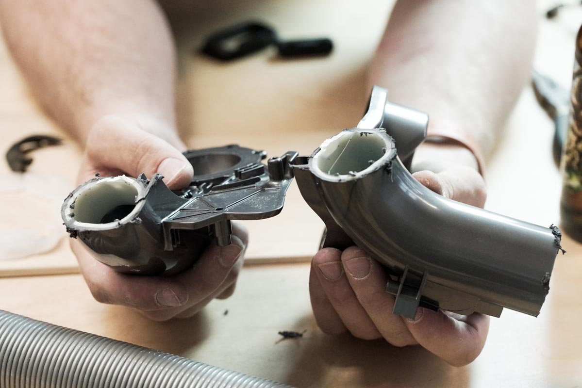
After disassembling all the components of the body we became fascinated by the curved injection molded ABS parts. At first glance it was challenging to understand how they created slides that went into the 180 degree tube pieces, but after some further investigation (and dremeling) we saw that the curved parts are actually 2 separate pieces welded together with a sleeve. It looks like an epoxy was used to weld the 2 ABS parts together to give a watertight seal. Remember, these tubes are holding the vacuum!
Another interesting note is that all the fasteners used are Torx screws: 6-point star-shaped security screws. While these fasteners are more expensive, they provide 3 key benefits:
1. They won’t strip during assembly
2. Protects Dyson from counterfeit
3. Makes it difficult for customers to disassemble their products (not us!)
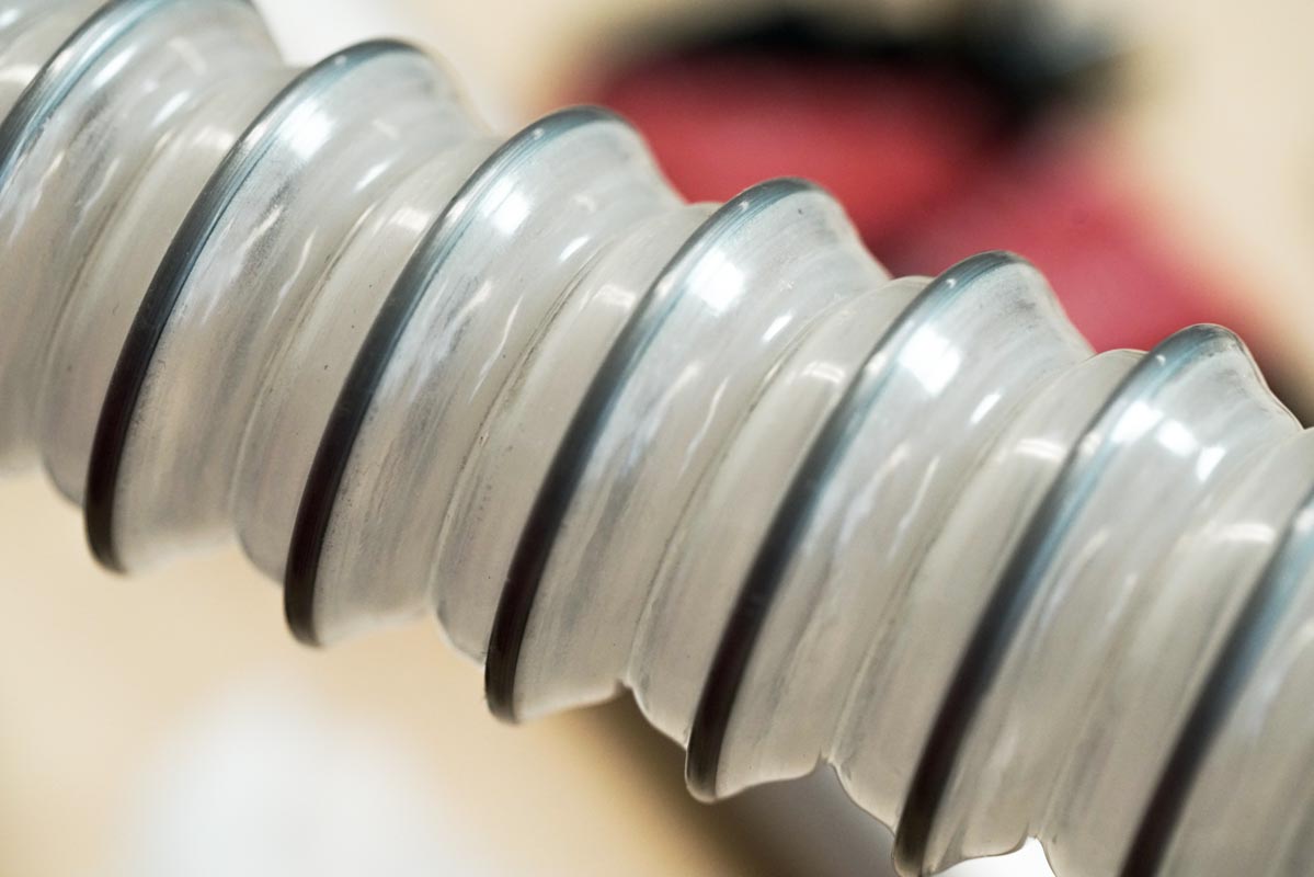
The clear accordian tube above would have been manufactured and then spray painted while closed to give it the silver color.
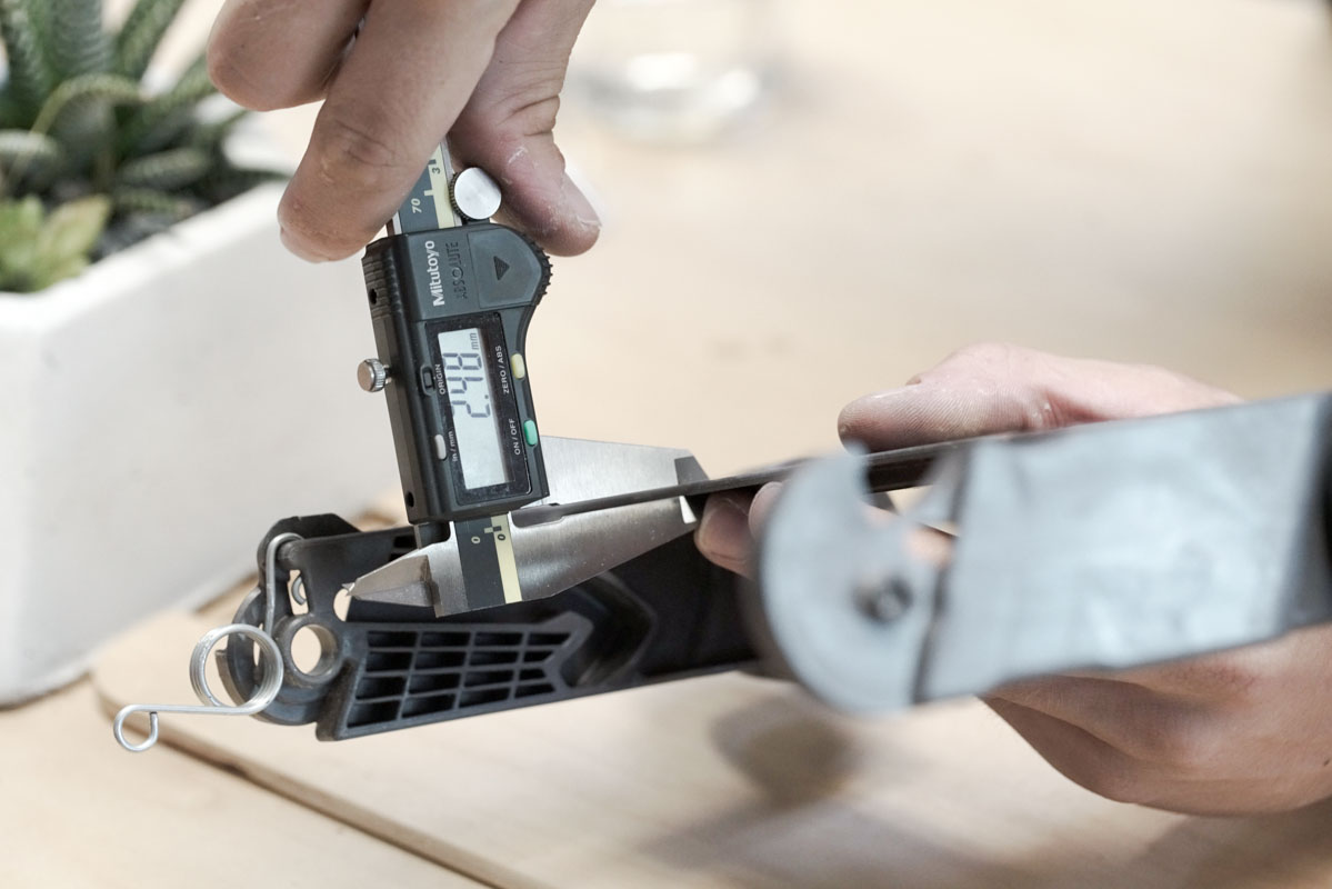
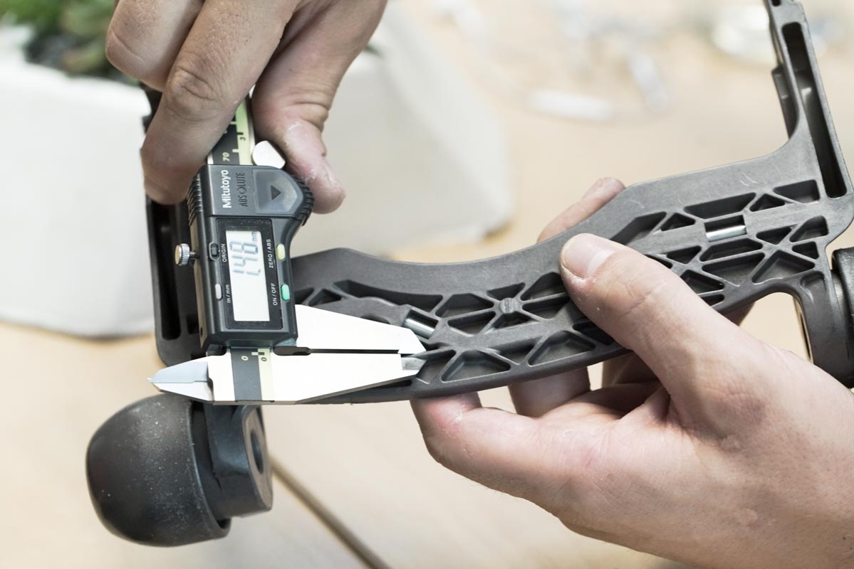
The final piece we found interesting was the foot brake. This component obviously needed to be very strong and the design and material choices certainly accomplish that need.
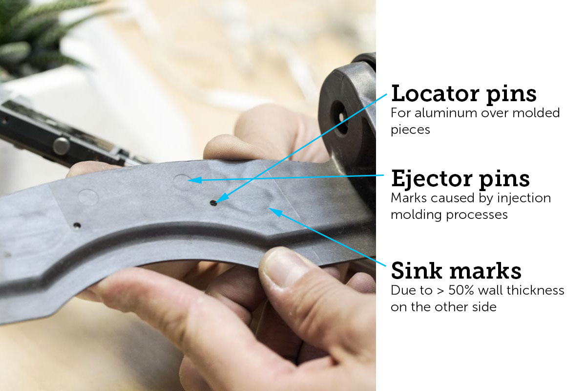
Again we see the standard 2.5mm wall thickness here with some very large 1.5mm ribs on the back (60% of the standard wall thickness). By now you can probably guess what that leads to… yup, sink marks!
But again, Dyson doesn’t seem to care about these small cosmetic imperfections—classic battle of function vs aesthetics.
We’ll also point out the overmolded aluminum rod used for additional strength here. You can see the locator pins on the top side and the open areas underneath where the pin would have been held in place while overmolding. This adds considerably more strength and allows the user to really press on the pedal without breaking it.