Time to read: 6 min
As one of the fastest and most precise manufacturing methods, it’s no wonder why injection molding is often chosen for mass producing plastic enclosures. Design for injection molding is therefore an important part of the enclosure design process, and following design for manufacturing (DFM) principles is a critical element of producing a successful product.
Today, everything from engineering components to cosmetic and custom product enclosures can be injection molded — as long as they meet the requirements for functional strength, appearance, durability, and resilience. A broad range of custom enclosures, electronic enclosures, PCB (printed circuit board) enclosures, industrial enclosures, and more are all good candidates for injection molding.
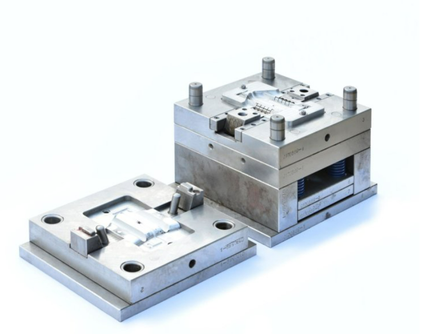
Designing Enclosures for Injection Molded Manufacturing
First, let’s define what enclosure design is and when it is used.
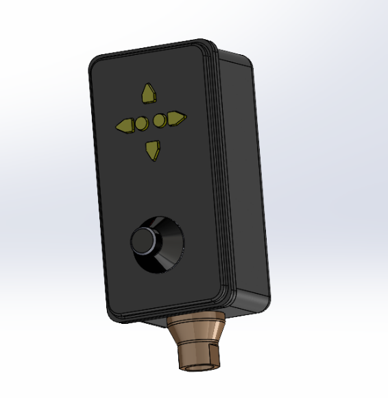
Enclosures are meant to protect mechanical or electronic systems from a final product’s intended surrounding environment. This environment may consist of high or low temperatures, dynamic or static loading, liquids like oil or water, and even acid-based solutions. In many cases, the product is only as reliable as the enclosure that protects it.
In this article, we’ll discuss how to make an enclosure for an industrial pallet jack. Typically, injection molding is used for large production runs of small, intricate parts. However, injection molding from Fictiv also supports prototyping and low-volume production.
Plastic injection molding is a process that injects liquid polymers into a mold at high pressure and temperatures. Plastics are good electrical insulators, but there are many different types of plastics and various types of hard plastics. The hardness of a plastic enclosure promotes its durability and provides environmental protection, but plastics are also a good choice for enclosures because polymers weight less and cost less than metals.
In this article, our focus is to explain the capabilities of the injection molding process and how to optimize the design of custom plastic product enclosures.
Injection Molding Design Guidelines
DFM needs to meet two critical requirements: aesthetic satisfaction and structural integrity. Therefore, product enclosure design is about more than just a creating a plastic box to house internal components. In many applications, a mechanical enclosure design will affect the final product’s service life and consumer appeal.
So, when an engineer is designing an enclosure for injection molding, there are many elements to consider.
Requirements
The enclosure design process begins by understanding the environment in which the enclosure needs to operate, the required enclosure functionality, and the standards required to protect the product. The design we’ve created for this article requires electrical insulation, light-weight functionality, and structural durability.
Enclosure design requires the engineer to follow some best practices to ensure the success of the final product. When designing a custom electronic enclosure for injection molding, keep the following considerations in mind:
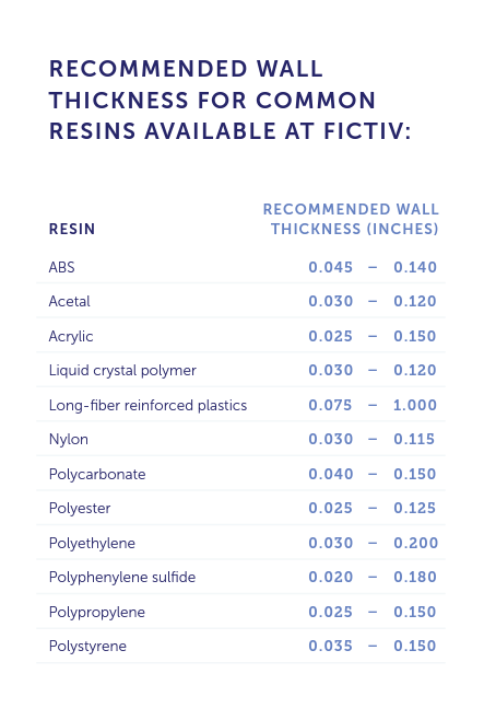
Wall Thickness is Critical to Design for Injection Molded Parts
Wall thickness is critical to the success and functionality of your design for injection molding. Wall thickness can influence many important factors, including cosmetics, mechanical performance, and cost to manufacture. To avoid delays in production scheduling, engineers need to design the enclosure with the proper wall thickness and ensure the right fit when it comes time for prototyping and manufacturing.
Further, it’s important to remember that the nominal wall thickness will be determined by the functional performance requirements of the enclosure. Establishing a nominal wall thickness depends on the enclosure’s expected service life and the amount of stress it must withstand. Enclosure walls that are too thin risk creating unforeseen air traps or other manufacturing issues. Similarly, walls that are too thick will be higher in cost because of greater material usage and longer cycle-times.
To avoid increasing costs, it’s best to maintain a consistent wall thickness throughout the entire part. A consistent wall thickness also allows for the turbulence-free flow of plastic resin — bear in mind that as plastic resin enters the mold cavity, it tends to flow into the part’s thicker regions.
Additionally, wall uniformity helps to avoid warping, sinking, and voids whiled improving mold fill. Variations in wall thickness will also cause the part to cool at an inconsistent rate, which increases cycle times and increases the likelihood of issues. Because plastics are poor conductors of heat, uniform thickness across the enclosure design ensures that the molten material cools uniformly and shrinks evenly as it solidifies. If it’s not possible to keep a uniform thickness in your design, you have several options to get quality parts.
Use Bosses and Ribs to Increase Structural Integrity
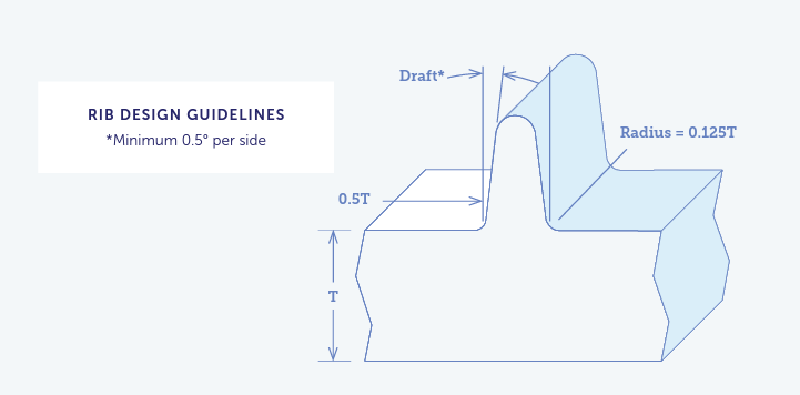
Because wall thickness is one of the most important factors in enclosure design for injection molded parts, the use of bosses and ribs to increase the structural integrity of thinner-walled areas is common. Designing to improve the stiffness of the enclosure can reduce the amount of material required to make the part. This also reduces the cycle time, resulting in a more cost-effective part.
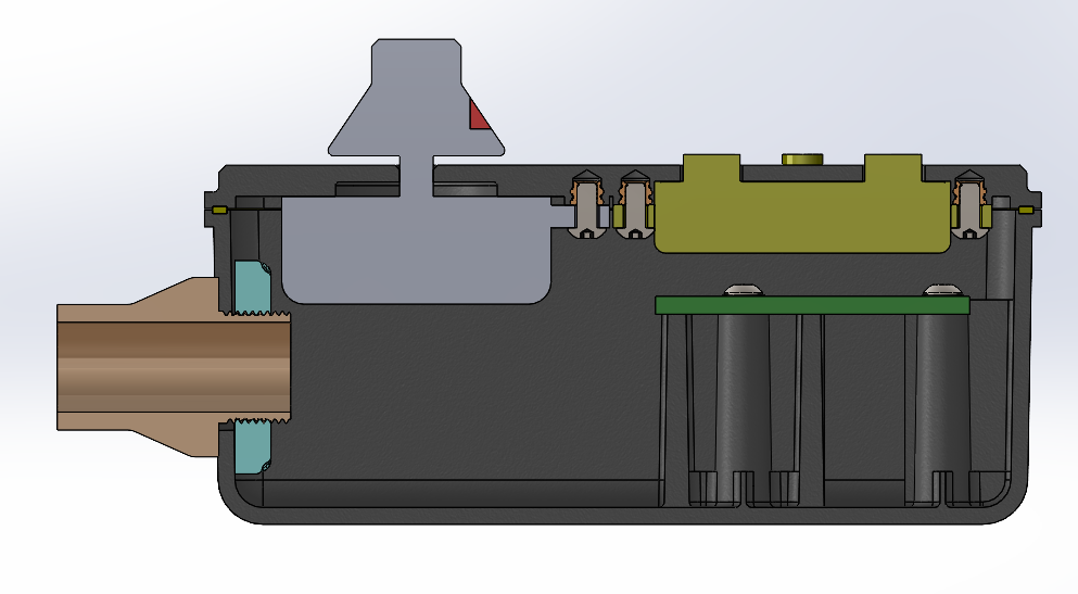
Incorporating ribs is a critical feature that should be considered for nearly all enclosures. Incorporating inner ribs will reinforce the overall structure, especially where attachment points are located.
Typically, plastic injection molded parts are designed to have a uniform wall thickness, but this rule can be broken when ribs are added. For example, injection molded wall thickness is usually in the range of 50%-75% of the nominal wall thickness. The bottom of the rib must feature a fillet that is somewhere near 0.25T-0.5T, where T is the nominal wall thickness. This radius should not be smaller than 0.010 inches.
It’s also important to keep the ribs as short as possible and to apply a minimum of 1 degree draft angle. Ideally, the height of the rib should not exceed 2.5T. Commonly used draft angles are somewhere between 0.5 degrees to 1 degree per side.
Our example plastic enclosure design pictured below incoporates ribs in the upper section where a printed circuit board (PCB) will be attached. This is also the location of the directional controls that will take repeated compressive loads. FEA (finite element analysis) should be used to simulate when the loads will occur, the magnitude of these loads, and the wall thickness required for the ribs.
Line of Draw
One of the first steps in developing an injection molded plastic enclosure is defining the line of draw on the part. That’s becaues the line of draw may limit the overall shape of the enclosure. The line of draw is located between the cavity and core of a mold where it will physically open to release the part, and there is only one line of draw per part. It’s also the locational feature of the electronics enclosure that defines both the parting line and draft angle.
Placing Parting Lines and Adding Draft
Depending on the end-product, the parting line (which determines the direction of draft and the pull direction) may be found right down the middle of the part — but designs with the parting line on a sharp edge is preferred.
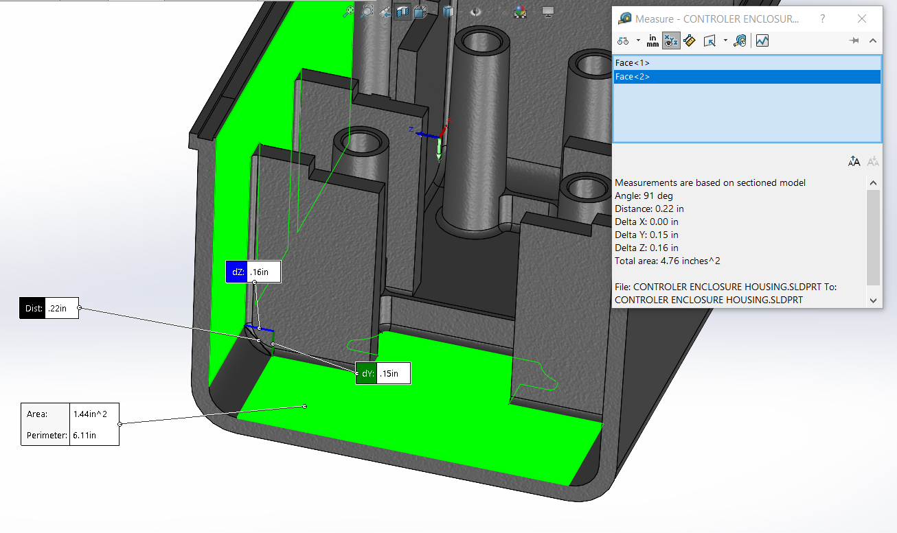
It’s good practice to avoid placing the parting line on a filleted surface. Doing so requires a tight tolerance mold, which increases costs, and any mismatch in the mold will lead to flash and potential cosmetic defects. This is why placing your parting line on sharp edges is ideal.
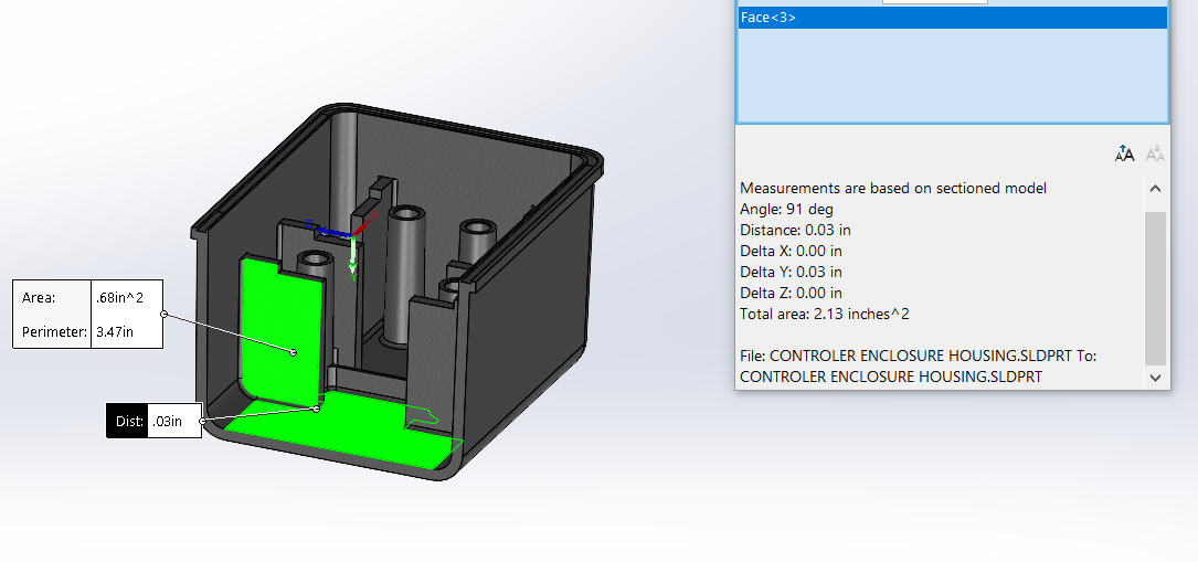
All injection molded parts must have a draft angle applied to all walls, which includes the primary structure, ribs, gussets, and bosses. For this electronics enclosure design, a draft of 1 degree has been added to all vertical features, since draft is critical for the part to release from the tool. Manufacturing a part without draft can lead to tool lock, which can cause severe damage to the part or tool during removal. Larger draft angles can be applied to the vertical walls of the enclosure depending upon the enclosure’s application — large drafts affect how the assembly is fitted and the chosen methods of attachment.
Conclusion
Understanding that product design has a direct effect on manufacturing costs is a key consideration in enclosure design. Knowing how to design enclosures that are feasible to manufacture, aesthetically appealing, and satisfy the application’s requirements are all key goals for design engineers. Due to its quick turnaround times and ability to to mass produce parts, injection molding parts for enclosure products will always be a popular choice.
Remember that mechanical product enclosures serve their purpose best when engineers optimize the design process using DFM best practices. If you’re looking to mold some custom plastic enclosures, we can help!
Fictiv is your operating system for custom manufacturing that makes prototype part procurement faster, easier, and more efficient. With our injection molding expertise and fast DFM feedback, we can help you build better injection molded enclosures, faster.
Fictiv lets engineers, like you, engineer — instead of sourcing, vetting, onboarding and managing suppliers. To get a quote and get to work, create an account and upload your designs today!


