Time to read: 9 min
Designing products for load bearing applications is a complex and multifaceted task, so it’s important for a designer to have a “toolbox” of techniques that improve design quality. Designing for part stiffness through geometric controls is one of these important tools.
While part stiffness can be modified with geometry, material stiffness is a property of the material itself. Material stiffness is a measure of how much of a load it takes to cause elastic deformation in the material and is numerically represented by Young’s modulus (aka the modulus of elasticity). A part’s stiffness is dependent upon both the material properties and its geometry, and is a measure of how much a component deflects when subjected to a given load.
Even the simplest designs can be sensitive to part stiffness. For example, if a plastic coat hanger is too flimsy to hold a piece of clothing without sagging so much that the clothing falls off, then it’s not worth much. This is why plastic coat hangers have a larger diameter (cross-sectional area) than metal hangers. No hanger designs come close to the material’s yield strength, but their function depends on the stiffness of the design.
This article is part one of a two-part series that discusses different methods for increasing part stiffness. Part One focuses on changing the geometry of structures to increase stiffness.
The overall concept of leveraging geometric relationships to increase stiffness in this manner is pretty simple, but the formulas can appear daunting. This is especially true if you don’t use them on a regular basis, so I’ll go over the process to clarify the math.
Pro-tip: Check out Part Two of this series, How to Design for Stiffness Using Material Properties. Also, for a review of terms we will use in this article, check out Engineering Fundamentals Refresh: Strength vs. Stiffness vs.Hardness.
Geometry Basics
When I say we’re going to increase part stiffness using a geometric approach, I really just mean that we’re going to make a part stiffer (less likely to deflect under a given load) with dimensional and/or shape changes. This may be as simple as increasing the diameter of a rod or as complex as adding gussets to certain bosses.
Consider a wooden board you are applying stress to at the end — a thinner board will deflect more under load than a thicker board. Due to the thicker board’s increased cross-sectional area (geometry), it can handle a greater applied load before deflecting.

Shapes and Sizes
A feature’s shape and size impact the formulas required for a calculation of stiffness, so let’s consider those geometric properties first. Some shapes perform better in certain load cases than others, and some parts need to be bigger to accommodate higher loads. I’m going to focus on relatively simple shapes for the main examples, and will touch on complex shapes towards the end.
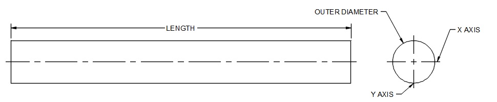
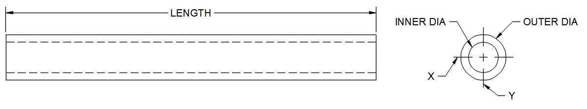
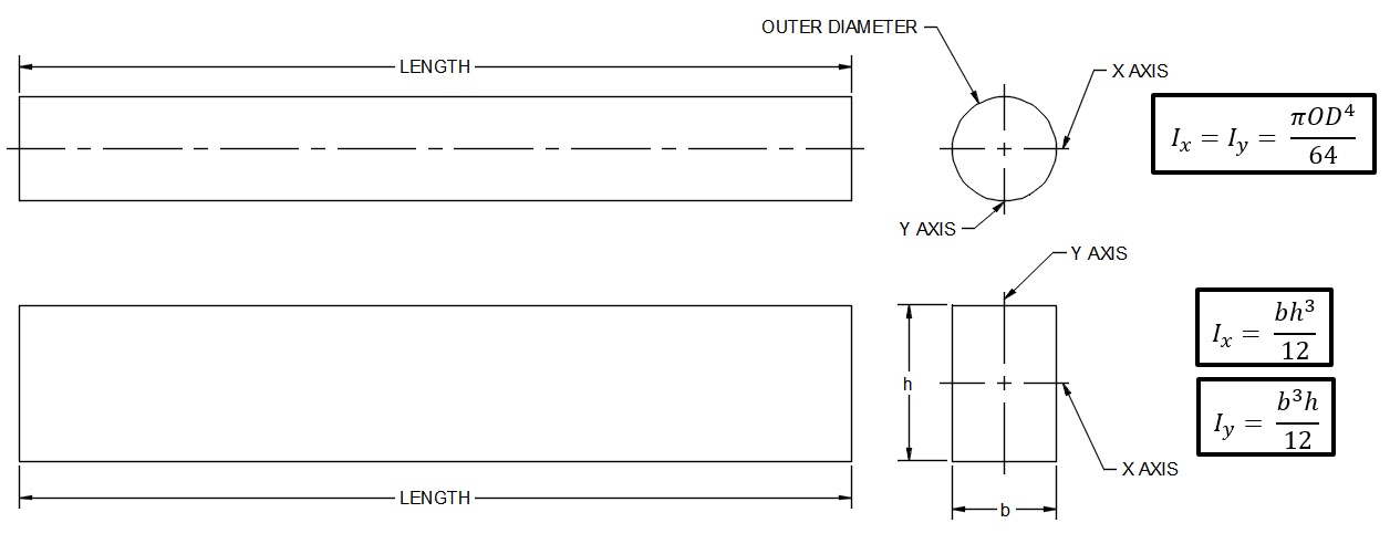
First up are round tubes and rods. For these shapes, the dimensions we need to consider are the outer diameter, the inner diameter (if we’re looking at a tube), and the length. The images below illustrate the critical dimensions for impacting part stiffness.
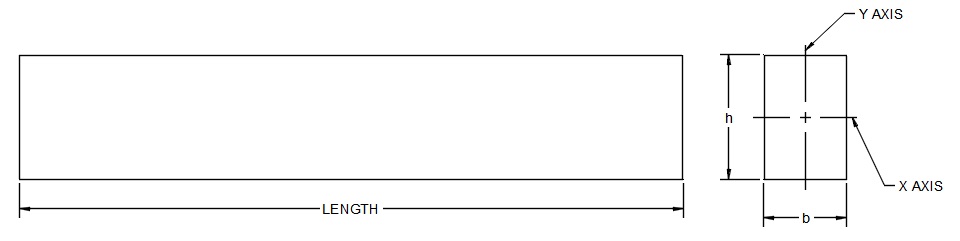
If we’re looking at square or rectangular bars, the dimensions of concern are different — we need to know the base, the height, and the length of the feature.
Problem Overview – Design for Stiffness and Rigidity
So, we know which dimensions are important, and we know that shape and size impact stiffness, but how big of an impact does it actually have? We can figure that out using the following mathematical approach.
Key Formulas
In order to solve problems related to stiffness, we need a few key formulas:
- Beam Deflection – This formula calculates the total deflection we’ll encounter in a beam when a load is applied. For our example, we’ll look at cantilever beams, but keep in mind that there are many different beam equations based on the load case.
- Beam Stiffness – This formula defines how resistant a beam is to deflection under a given load. As beam stiffness increases, deflection under load decreases. This formula is based on the beam deflection formulas below.
- Area Moment of Inertia (Area MOI) – This formula takes into account the geometry of our beam and is used to solve our deflection and stiffness formulas.
There are only a few formulas required to solve for stiffness, but each geometry and load case may have a different formula.
Beam Deflection and Stiffness
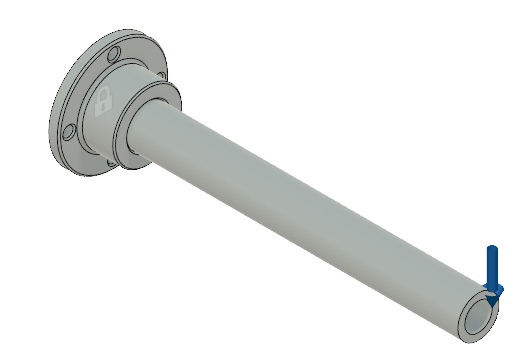
Our first formula defines the deflection of a cantilever beam with a load at one end. The image below illustrates what this means.
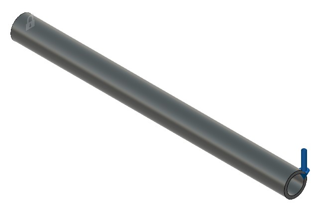
On the left end of this tube, we can see a picture of a lock. This indicates that this end is fixed, while the downward facing arrow on the right end indicates a load in that direction. Now, if we go back to the formula to define how much this rod will deflect, we’re left with the equation below:
δ= PL33EI
Where:
- δ= Deflection
- P = The Force Applied at the End
- L = The Length of the Rod
- E = Elastic Modulus
- I = Area Moment of Inertia (MOI)
The area MOI is calculated with another formula (based on geometry), which we’ll touch on in the following section, but first we’ll look at stiffness. We already know that stiffness is directly related to deflection, but we still need to derive the formula. To do this, it’s beneficial to remember that stiffness is typically represented as a spring constant, k. And we know that the spring constant is defined as force divided by deflection, which gives us the following formula:
k= Fx
where:
F = P
x = δ
gives:
k= Pδ
Solving for deflection, we get the following formula for stiffness:
k= 3EIL3
As shown by the above equation, the geometry is at the core of the part stiffness because the area MOI, or ‘I’ is dependent on part geometry.
Next, we’ll solve for both stiffness and deflection, just to demonstrate how they correlate (if the derivation hasn’t sold you already).
Area Moment of Inertia
The final formula we need to know for our analysis is the area moment of inertia (area MOI). This formula is the heart of our geometric stiffness control method because it incorporates the exact dimensions and shapes we’ll be modifying. First, let’s revisit our tube geometry below.
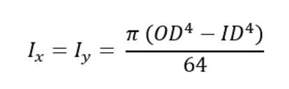
When it comes to calculating the area MOI for a tube, the only dimensions we will need are the Outer Diameter (OD) and Inner Diameter (ID). The formula for a tube’s area MOI is shown below:
Ix=Iy= π (OD4-ID4)64
Where:
- Ix= Area MOI about the x axis
- Iy= Area MOI about the y axis
In this example, the area MOI is the same about both axes, but with shapes like rectangles, that’s not always the case. The best way to understand which moment of inertia to consider is to think about applying a load — around which axis will the bar rotate or wrap? As an example, if we place a load parallel to the Y-axis in the example above, we’ll try to rotate the bar around the X-axis. That means we’ll need to consider the area MOI about the X-axis.
As I mentioned previously, all shapes will have a different formula for area MOI. The images below detail a round rod and a rectangular rod with their associated formulas.
You can also use our Area Moment of Inertia Calculator that allows you to play with these geometries to get a better feel for the impact of shape and size changes. There’s even a tab for part stiffness and deflection that will allow you to estimate the deflection if you don’t have an FEA program at your disposal.
Part Stiffness Calculation Example
Now that we know the formulas, let’s put them to use with our Area Moment of Inertia Calculator to provide a method for how to calculate stiffness and deflection. We’ll start by looking at the parts and load case shown below:
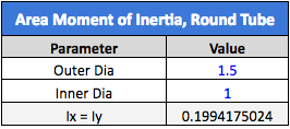
The base of the assembly is fixed to the wall, while a tube is inserted into the base to hold a load, as indicated by the blue arrow. In this example, the tube has an OD of 1.5” and an ID of 1.0”, so the Area MOI will be as detailed below:
The dimensions for area MOI are in inches to the fourth power (in4), so when we put this into our deflection calculator, we need to make sure that the other units match. Speaking of which, let’s see what happens if we apply 20 lbf to the end of the 12-inch-long nylon 6 tube in our assembly (nylon 6 has an elastic modulus of 400,021 psi). We’ll put all the important information into our deflection calculator, as shown below:
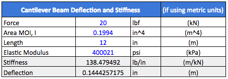
Our calculator predicts that the beam will deflect 0.144” at the end, which sounds like a pretty reasonable number. Let’s see what we get if we actually run this assembly through an FEA study.
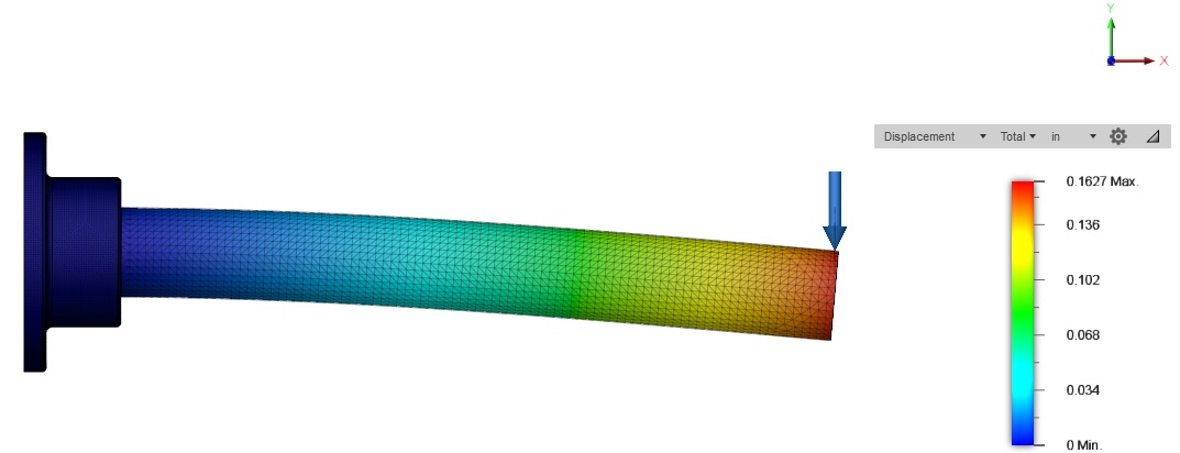
Here, we can see that we got about 0.163” of deflection at the end. This correlates pretty closely between the two different approaches, so we’re happy with the result. The differences may be a result of the deflection spreadsheet approximating the interaction at the base, as well as small calculation margins combined between the FEA (which likely uses a more complex 3D stiffness matrix approach) and generalized deflection equation.
Now, to increase the part’s stiffness, we will increase the part’s OD to 2.0” and the ID to 1.5”. In doing so, we get the following area MOI.
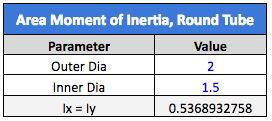
We have only increased the OD by 33%, but the area MOI has increased by about 170%. Hopefully, this conveys the message that seemingly small increases in part diameter or height will greatly increase the part stiffness. Now, let’s run the calculations for part stiffness and deflection.
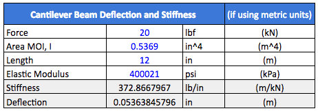
This time, we can see that the stiffness has also increased by 170%, and deflection has demonstrated an inversely proportionate relationship. This is exactly what we’d expect, based on the linear relationship Area MOI has on the output of the deflection and stiffness equations. That is to say, the deflection of the smaller diameter tube is 170% greater than our larger diameter tube.
Now, let’s jump over to an FEA study that looks at our 2.0” OD by 1.5” ID cantilever tube and compare the result, as shown below.
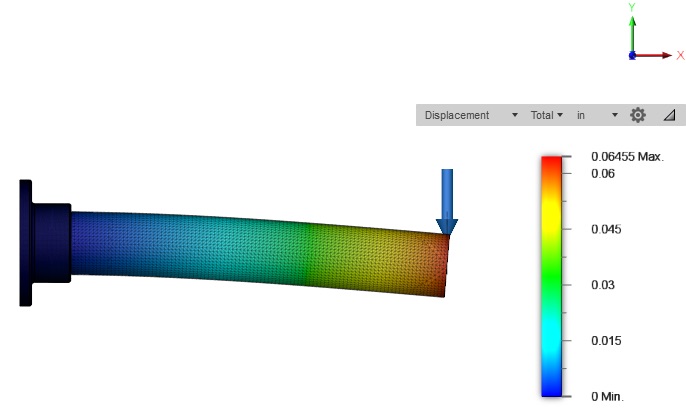
We can see that the deflection is 0.0646”, which is pretty close to our spreadsheet calculations again. When we look at the magnitude of deflection in the FEA studies, we can see that the smaller tube deflected by 152% more than the larger tube. Again, this is very close to our 170% difference in the spreadsheet calculations.
Stiffness Principles, Solid Bar vs. Tube
Also worth noting is the stiffness performance of the tube as compared to solid bar stock. While the tube contains less material and mass, it can be designed to have almost the same stiffness as a similarly sized solid bar. Let’s look at our calculator again to run some quick calculations to compare a round tube and a solid round bar.
The first calculation we’ll run is going to look at a 2” round tube with a 1” bore through the middle. We will compare this with a 2” solid round bar, as shown below.

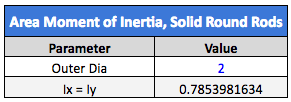
The round tube is almost as stiff as the solid round bar, even though the center is hollowed out. This is useful if we need to save weight and/or material. Obviously, a hollow tube weighs much less than a solid bar, and the reduction in material equates to savings. If we need the stiffness to be about the same, we don’t have to add much to the outer diameter.
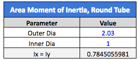
We’ve matched our original stiffness after adding just 0.030” to the outer diameter, while keeping the 1” internal diameter for our tube stock. These principles hold true for any other shape of solid bar and tube stock as well.
Other Methods to Determine Stiffness
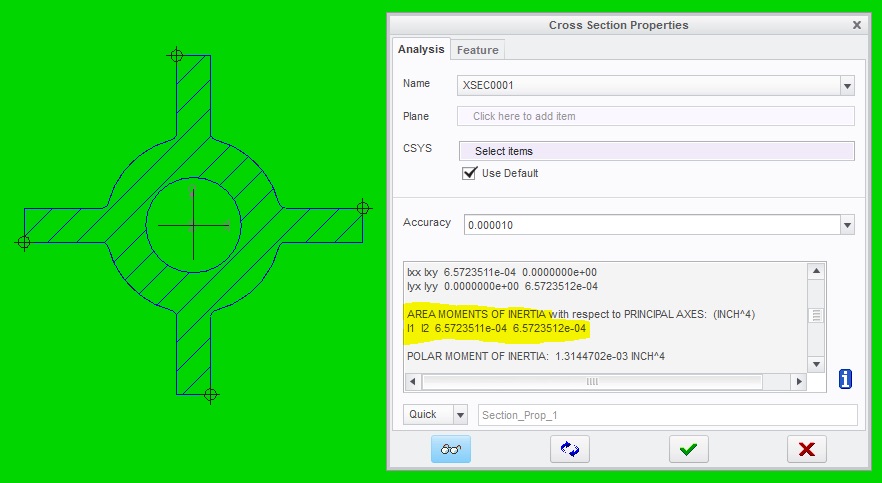
There are other methods for determining part stiffness, area MOI, and deflection — an FEA study is the first that comes to mind. However, we may not always have access to a good FEA program. If that’s the case, we can get the area MOI from our CAD program. Both Solidworks and CREO/ProE have this function, which is especially useful when looking at complex geometries. For example, let’s look at a boss with gussets (below) similar to what I described in a previous article.
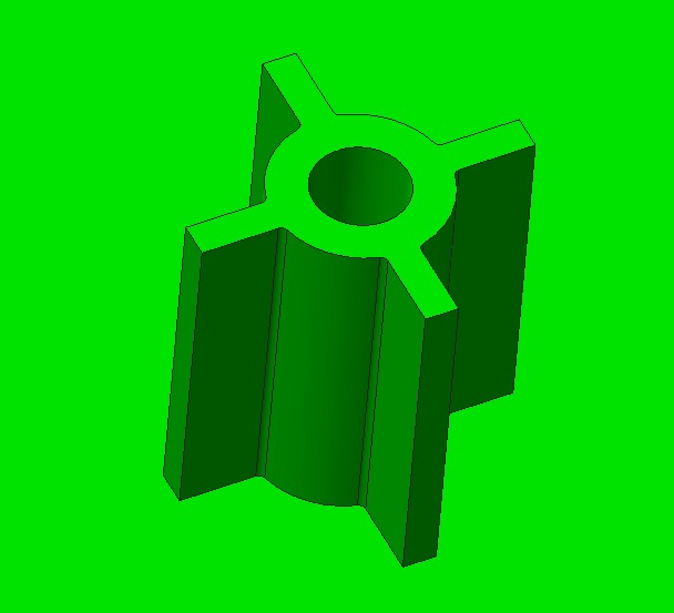
You can see that the boss is not simply a cylinder, it includes gussets that make it a little harder to calculate the area MOI. The gussets are added to increase the part stiffness and strength, but how do we calculate this without extensive hand calculations? By looking at the cross section properties in your CAD program to determine the area MOI.
Now, we can quantify the exact increase in stiffness achieved by this modification based on these measurements.
Main Takeaways
Now you know the basic principles of designing for stiffness using a geometric approach, the stiffness calculation for a beam, and how to achieve the goal of stiffer parts for higher quality designs. Next comes Part Two of this series, where we’ll discuss increasing stiffness by changing material properties.
Sourcing Simplified – Start Your Next Project With Fictiv
Having mastered the art of modifying part stiffness using a geometric approach, you may need to source a supplier to manufacture your expertly designed parts. Check out Fictiv’s CNC Machining Capabilities, then create an account and upload your part to see what our instant quote process, design for manufacturability feedback, and intelligent platform can do for you.
Fictiv is your operating system for custom manufacturing that makes part procurement faster, easier, and more efficient. In other words, Fictiv lets engineers, like you, engineer.