Time to read: 15 min
This article was originally published in February 2017 by Humberto Villasenor. The content has been updated.
Understanding the differences between the mechanical properties of strength vs. stiffness vs. hardness is foundational in mechanical engineering, yet these properties are often confused. These properties are related, but they have important differences:
- Stiffness is an indicator of the tendency for an element to return to its original form after being subjected to a force.
- Strength measures how much stress can be applied to an element before it deforms permanently or fractures.
- Hardness measures a material’s resistance to surface deformation. For some metals, like steel, hardness and tensile strength are roughly proportional (see ASTM A 370-68 Steel Tables).
For this article, we’ll review the fundamentals of each, identify common pitfalls differentiating mechanical strength vs. stiffness vs hardness, examine the technical differences between the three, and discuss their relevance in the selection of materials for product development.
It’s especially easy to confuse strength vs stiffness. If a material is stiff, then it must be strong enough to support a large load, right? So, aren’t strength and stiffness the same? No! A material can be strong and elastic or strong and stiff (See section “Axial Loading on a Straight Member”), but strength and stiffness are two separate qualities — there are many types of material strength, including tensile and yield strength.
Key Definitions
- Yield strength is used to describe materials that exhibit elastic behavior. It’s the maximum tensile stress the material can handle before permanent deformation.
- Ultimate strength refers to the maximum stress before failure occurs.
- Fracture strength is the value corresponding to the stress at which total failure occurs.
- Stiffness is how a component resists elastic deformation when a load is applied.
- Hardness is resistance to localized surface deformation.
Tensile strength can be calculated from hardness and is easy to determine because hardness tests — such as Rockwell — are simple to perform, inexpensive, and non-destructive because only a small penetration is performed on the specimen. For many metals, tensile strength increases as hardness increases.
Young’s Modulus
Young’s Modulus stress-strain curve is a great reference tool for understanding the relationship between stiffness and strength. Young’s Modulus (aka elastic modulus, shear modulus, or bulk modulus) defines a material’s ability to resist elastic deformation while under loading conditions and is the ratio of normal stress to normal strain. In basic terms, this tells us how easily a material can stretch and deform.


Stiffness
Stiffness is a material’s ability to return to its original form after being subjected to a force. Strength is how much stress can be applied to a material before it goes into plastic deformation or fractures. Stiffness and elastic modulus are related: as the elastic modulus goes up, the stiffness of a material also goes up. Since stiffness and strength are related to the elastic modulus of a material, you can look up the elastic modulus in a material properties reference handbook to determine the strength and/or stiffness of a given material.
The stiffness of a material can be quantified by the slope of the stress-strain curve, as illustrated in the graph below. There are many types of stiffness to consider, depending upon your application, including tension/compression stiffness, axial force ratio, axial linear strain (EA), torsional stiffness, bending stiffness, beam stiffness, spring stiffness, and shear stiffness. In general terms, the stiffness of a material is calculated by using the following equation:
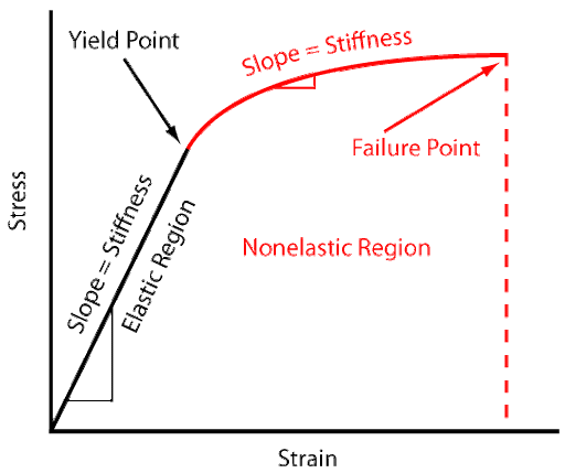
The Young’s modulus stress-strain curve shown above is a good way of graphically demonstrating stiffness. The ratio of stress to strain is the elastic modulus (stiffness), but the way a material responds to stress, and only the stress, defines the strength of the material.
Pro-Tip: Check out How to Design for Part Stiffness Using a Geometric Approach for a deeper dive into stiffness and how it’s related to part geometry.
Strength
Strength measures how much stress a material can handle before permanent deformation or fracture occurs. Both tensile strength and hardness are indicators of a metal’s resistance to plastic deformation. Multiple types of strength are worth considering depending on your application, including ultimate tensile strength vs yield strength. Ultimate tensile strength is the maximum stress a material can withstand before it fails or breaks (which is the failure point in the graph above). Yield strength is the maximum stress a material can withstand before plastic deformation occurs (which is the yield point inthe graph above). Simple stress-strain curves illustrating stiff vs non-stiff behavior. Curves A and B correspond to stiffer materials, whereas curve C represents a non-stiff (ductile) material. (Image source)
Pro-tip: If you want more information on how materials respond to stress and how to determine the strength of materials, check out Strength Theory.
Hardness

Hardness is a measure of a material’s ability to withstand plastic deformation or a material’s resistance to penetration by a pointed tool. This is a critical characteristic to consider in applications with two materials impacting each other — the harder one will scratch or cause plastic deformation on the other material. Hardness is dependent upon ductility, plasticity, strain, strength, toughness, viscosity, and viscoelasticity. It’s an important measure when considering the wear resistance (abrasion or erosion resistance of a part) since harder materials typically have higher wear resistance.
Hardness testing is accomplished by lowering a probe with a hard (typically diamond) tip onto a material at a set force and measuring the amount of indentation that the probe (the indentor) produces (depth of plastic deformation). Hardness testers also operate by measuring the size of the impression left by the indentor.
Understanding Stress and Strain
Stress is an internal force resulting from an applied load; it acts on the cross-section of a mechanical or structural component. Strain is the change in shape or size of a body (deformation) that occurs whenever a force is applied. There are two types of strain that correspond with the two types of stress:
- Normal Strain: deformations that occur perpendicular to the cross-section; normal strain is caused by normal stress
- Shear Strain: deformations that occur parallel to the cross-section; shear strain is caused by shear stress
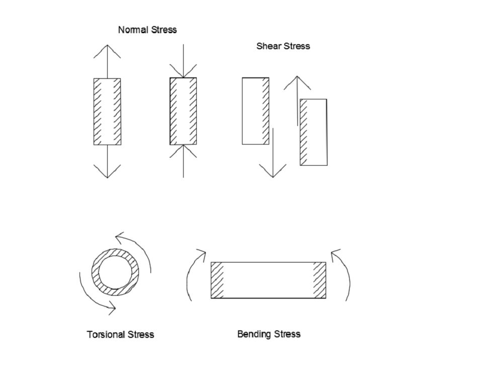
Top left: axial load causing tension or compression. Top right: shear stresses within a member. Bottom left: torsional stress about a circular cross-section. Bottom right: Bending stress caused by a moment.
Examples: Strength vs. Stiffness
To further understand the difference between strength and stiffness, let’s go back to the basics of how we were or were probably initially taught about strength and stiffness. Utilize the following examples and downloadable calculator as thought exercises to deepen your understanding of the concepts of stiffness vs strength.
Beam Deflection
The image below is a finite element analysis (FEA) rendering of a beam subjected to a load. The beam’s response to the loading is a deflection resulting from internal bending and shear stress. If the internal stresses exceed the yield strength of the beam’s material, then you need a material with a higher Young’s Modulus value — a material with higher stiffness (to resist deformation) and also higher yield strength (to prevent permanent deformation and possible fracture).
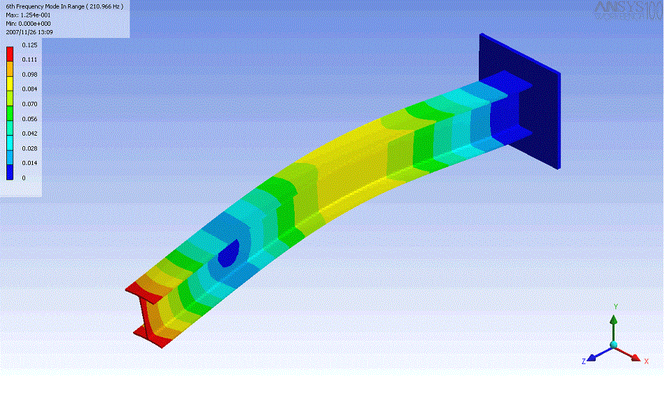
Finite Element Analysis of beam deflection.
Area Moment of Inertia Calculator

If you’re looking for a simple way to calculate the Area Moment of Inertia for a round tube, solid tube, or rectangular beam — or to calculate deflection and stiffness for a cantilever beam — you can use our Area Moment of Inertia Calculator. This tool also allows you to play around with geometry to understand how the cross-sectional shape of a part impacts stiffness and deflection.
Axial Loading on a Straight Member – Stiffness
To further understand stiffness, let’s consider a metal bar in tension, subjected to an axial load (bending moment). The internal stresses cause a deformation of 1% of the metal’s original length when it breaks at 100 lbf.
Next, consider a rubber-like rod-shaped polymer that’s subjected to the same force but deforms 5% of its original length and breaks at 100 lbf. Both materials are equally strong, but the metal is stiffer than the polymer, which means that it deflects less for the same given loading condition. This thought exercise is a great way to show that as stiffness increases, the amount of deformation for a given load decreases.
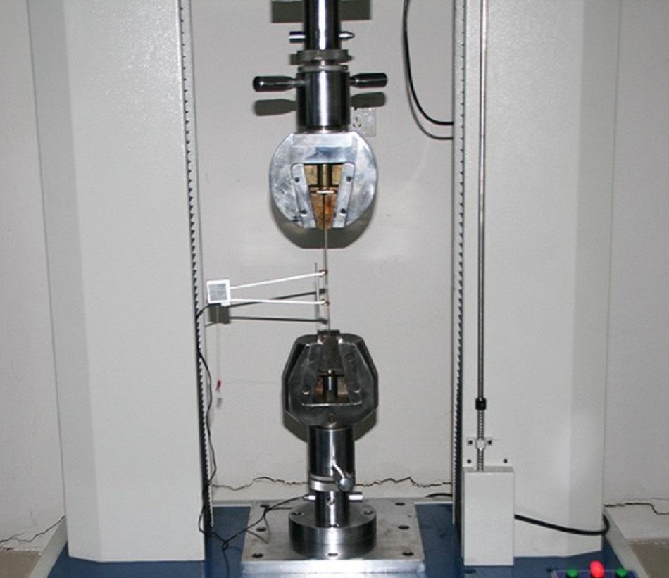
Tensile strength test.
Thermal Stress
Thermal stress also affects the deformation response of a component that is already subject to some force — thermal stress affects the strength of materials. Consider a case of a bar with a force applied to it that is also exposed to a temperature differential, causing a temperature gradient within the member – and therefore thermal stress; the thermal stress induces additional strain to the strain already imposed by forces acting on it. For example, metals expand when heated and contract when cooled, which stresses the material, and when coupled with any externally applied stress from loading, the metal will fail more rapidly. Here is the method for calculating thermal stress:
𝜎=𝐸𝛼Δ𝑇
𝜎=E𝛼ΔT
𝜎 = thermal stress
Where α = coefficient of thermal expansion
ΔT = difference in initial temperature and final temperature
E = Young’s Modulus
The equation above shows how thermal stress is dependent on Young’s Modulus, or the stiffness of a material. Computing thermal stress provides insight into what values of stiffness and strength are appropriate for your design (assuming the temperature difference is not large enough that it will change the microscopic properties of the material). Learn more about using thermal properties for material selection in this article, Heat Exchanger Material Selection.
Retrieving Mechanical Property Data
If you’re looking for the mechanical (or thermal or electrical) property data of a given material, you can get it from the American Society for Testing Materials (ASTM) or by consulting the material manufacturer’s website. Typically, the data values available range from material stiffness and mechanical strength to hardness and tensile strength. MatWeb is a particularly useful resource with accurate data that can be obtained quickly.
Pro-Tip: If you are new to reading material data sheets to obtain mechanical property data, check out this resource, How to Read Material Data Sheets.
Best Practices Designing for Strength, Stiffness, and Hardness
Here are three best practices to keep in mind throughout the design process:
- Identify Critical Components First
In the early stages of your design, such as when constructing the CAD model (learn more about CAD design terms in this article), determine which components will be critical to your design — aka, which ones will be subjected to impact loadings, uniform loadings, concentrated loads, constant loads, etc. Doing so gives you an idea of the stiffness or strength you need for those components. It’s also a good idea to develop graphical representations of complex dynamical systems using bond graph or block-diagram modeling and utilize software to model sophisticated systems.
2. Determine Applied Forces to Each Component and Calculate Stress
Next, calculate the expected stresses on mechanical components to determine where problems may arise or where forces are large. Measure how the design responds to various inputs using instrumentation techniques and perform data analysis to predict your model’s behavior. Consider creep and fatigue variables in subsystems and those associated with the environment to which your system will be exposed. For a refresher on calculating stresses that designed components are subjected to, I recommend consulting this mechanical engineering design book.
3. Best Practices for Material Selection
As previously discussed, each material type has its own set of mechanical, thermal, and electrical properties. Different materials are optimal for different applications. For example, ceramics are usually brittle, meaning that there’s hardly any deformation before fracture. So, cracks may spread rapidly with little accompanying plastic deformation. In contrast, metals exhibit two modes in response to an applied stress: ductility or brittleness. Ductile materials are accompanied by plastic deformation before fracture, while brittle materials are not.
If you are looking for a resource on selecting the best material for CNC machining in the face of competing requirements, check out this resource, Your Guide to Picking the Best CNC Materials for Machining.
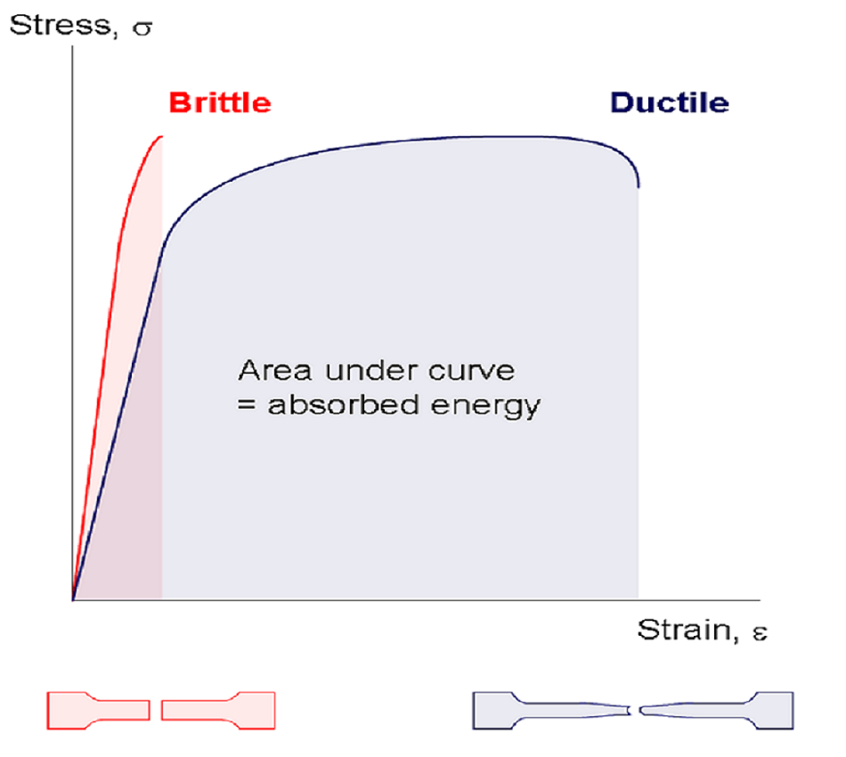
Figure 7. Ductile vs. Brittle
The fracture process for ductile metals normally occurs in several stages (ductility and brittleness in polymers depend on temperature). For raw materials, determine which manufacturing processes will provide you with the desired material properties. Testing of materials should conform to ASTM standards, so consult engineering handbooks to obtain reliable material data.
In addition, materials should be selected based on the environmental conditions the components will be exposed to. The chemical composition of a material determines its ability to withstand environmental conditions such as water, salt solutions or even chemical corrosion. Stainless steel, aluminum, and titanium are good material choices when environmental resistance is necessary. Bear in mind that a material’s hardness plays a role in determining whether or not it can withstand abrasive environments such as desert conditions. As a rule, your material should have a higher hardness than the abrasive materials it may come into contact with to prevent material loss.
4. Verify Designs Before Prototyping
Design optimization and verification should be performed prior to prototyping a design, and CAD software can assess and optimize the geometry of your design. FEA analysis and numerical analysis are a good idea, and when feasible, double-check your analysis with hand calculations before prototyping begins to save time and money. Also, consult with other engineers for review.
It’s also critical to consider design for manufacturability (DFM) when optimizing a design prior to production. Even the most intelligent designs will fail if they don’t account for the limitations of manufacturing methods. That’s why Fictiv offers instant DFM feedback for every design that’s uploaded to our platform.
Main Takeaways
The proper understanding and implementation of stiffness, strength, and other mechanical properties in your design process is critical for building high-quality products. A clear understanding of a product’s intended use is key for choosing appropriate materials that are cost-effective, safe, and have the required structural integrity to achieve the desired performance. Here are a few things to keep in mind when making your material selections:
- Mechanical strength measures how much stress can be applied to an element before it deforms permanently or fractures.
- Stiffness in mechanical engineering is an indicator of the tendency for an element to return to its original form after being subjected to a force. If you are looking for a simple way to calculate the stiffness of a cantilever beam, check out our Area Moment of Inertia Calculator.
- Hardness measures a material’s resistance to surface deformation.
- Young’s Modulus quantifies the amount that a material is able to resist elastic deformation under loading conditions. A stiff material has a high Young’s Modulus and is able to hold its shape minimally when subjected to elastic loads.
- Ultimate Tensile Strength, referred to as Tensile Strength, is the maximum tensile load a material can withstand prior to fracturing.
Sourcing Simplified
Navigating the complexities of sourcing materials with the ideal strength, stiffness, and hardness for your project can be daunting. Fictiv simplifies this process, acting as your one-stop shop for custom mechanical parts. Whether you’re exploring CNC machining, injection molding, 3D printing, or other processes, our engineering experts are here to assist you in selecting the perfect material for your application. We guide you seamlessly through the manufacturing stages, ensuring outstanding results.
Experience the ease of our platform by creating an account and uploading your design.
For further learning, check out these Fictiv resources:


