Time to read: 9 min
In engineering, the term “fit” describes the relationship between two mating parts, such as a shaft and a hole. The way these parts interact—whether they fit snugly together, move freely, or press into one another—is crucial to the performance and functionality of the mechanical system.
The correct fit ensures that parts function optimally, whether they need to rotate smoothly, stay in place under stress, or move with precision. Understanding the different types of fits and their applications is essential for engineers who design and manufacture mechanical parts and assemblies.

This article will explore the three primary types of fits used in engineering: clearance, transition, and interference (press) fit, as well as the importance of tolerance in selecting and applying these fits effectively.
What Are the Types of Fit in Engineering?
At the heart of every mechanical assembly is the relationship between parts—their dimensions and how they interact with each other in points of contact. Fit refers to the relationship between two mating parts—typically a shaft and a hole. The fit determines whether the parts can rotate, slide, or remain fixed in place.
There are three primary types of fits in engineering: clearance, interference, and transition.

Types of Engineering Fits
Clearance Fit
A clearance fit is the most common type of fit, where the hole is always slightly larger than the shaft, creating an intentional gap between the two parts. This gap, or clearance, allows for free movement without friction or interference and is controlled by the tolerances of both component features to ensure a smooth fit without excessive looseness.
There are various types of clearance fits including slide fit, easy slide fit, loose running fit, free running fit, and close running fit. These are based on the amount of clearance and looseness of the fit.
Clearance fits are ideal in applications where movement, rotation, or easy assembly is required. Examples include:
- Bearings: Allow shafts to rotate freely without binding.
- Linkages and sliding parts: Enable easy insertion and removal with minimal force.
- Gears: Permit smooth rotation while preventing tight contact.
- Plumbing fittings: Facilitate simple assembly and disassembly by allowing pipes to slide easily into connectors.

Interference Fit
An interference fit, also known as a press fit, occurs when the shaft is slightly larger than the hole, resulting in a tight, force-fit connection. The parts are assembled under pressure (or by applying heat to the hole, which temporarily expands it before fitting), creating an interference that prevents any movement between them. This fit forms a strong, stable bond that is often permanent or semi-permanent.
Interference fits are used when components must remain fixed under load, vibration, or stress. Common applications include:
- Press-fit assemblies: Ensure secure, immobile joints.
- Gears and pulley systems: Prevent slipping by tightly locking components onto shafts.
- Bearing assemblies: Securely hold inner or outer races in place to prevent rotation or displacement during operation.
- Automotive wheel hubs: Maintain a firm connection between wheels and axles.

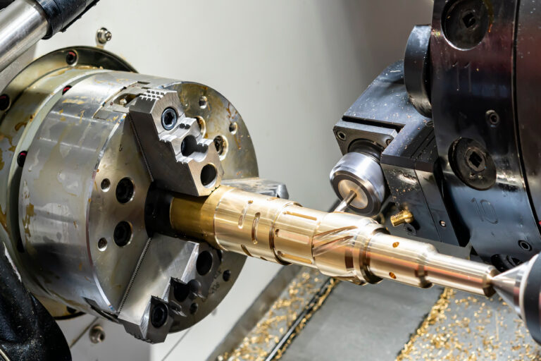
A shaft gear bearing typically uses interference fits.
Transition Fit
A transition fit strikes a balance between clearance and interference fits. Depending on the exact tolerances applied, it can result in either a small clearance or slight interference between the shaft and the hole.
This type of fit is used when precise alignment is needed, and parts must fit together tightly—but not permanently—allowing for minimal play and controlled movement.
Transition fits are ideal for applications requiring both stability and ease of assembly. Common examples include:
- Tooling Fixtures: Ensure accurate alignment with minimal movement.
- Precision Assemblies: Used in engine components and machinery where tight control is critical.
- Bearings: Help regulate contact with inner and outer races, minimizing movement without creating excessive friction.

Tolerance Considerations for Each Fit Type
Engineering tolerance defines the allowable deviation from ideal dimensions, ensuring parts fit within desired parameters. It specifies the acceptable variation in shaft and hole dimensions (as maximum and minimum sizes), as no manufacturing process is perfectly precise.
Tolerances apply to any mating parts, including gears, bearings, and fasteners. Tolerance affects how well parts fit based on the capabilities of the manufacturer.
Engineers must utilize GD&T and balance the need for tight (precise, costly) and loose (cheaper, less precise) tolerances. Tight tolerances are crucial for precision, while loose tolerances can reduce costs but may cause misalignment if they are not designed around.
Tolerance selection is driven by the functional requirements of the part and its features. There are international standards for tolerances, such as ISO 286 and ANSI standards, which provide a framework for defining tolerances. These standards ensure that parts manufactured in different regions or by different manufacturers can fit together reliably.
How to Choose the Right Engineering Fit
Choosing the right fit begins with a clear understanding of the functional requirements of the parts and their intended application. It also involves evaluating several key factors to ensure proper performance, alignment, and durability.
Key Factors for Choosing the Right Engineering Fit
| Factor | Description |
| Load and Stress | Fits must handle expected loads and stress. Interference fits are suitable for high-load, permanent connections, such as in bearings and gears. |
| Movement or Lack of Movement | Choose a clearance fit for unrestricted movement or an interference fit for a fixed connection. |
| Manufacturing Considerations | Fit selection should match manufacturing capabilities; casting can require looser fits, while precision machining allows tighter tolerances. Ensure cost-effective production with available equipment. |
| Cost Considerations | Tight tolerances are more expensive to achieve. If a particular fit isn’t critical for performance, opting for a looser tolerance can save on manufacturing costs without compromising the part’s functionality. |
| Material Considerations | Material properties—such as stiffness, thermal expansion, and yield strength—impact fit behavior. Softer or high-expansion materials may require looser fits to avoid deformation or tolerance drift. |
| Practical Considerations for Tolerance Selection | Engineers must balance precision, cost, and manufacturing limits. Tight tolerances ensure fit but raise costs, while loose tolerances reduce costs but may affect performance and longevity. |
Table 1: Key Factors for Choosing the Right Engineering Fit
Selecting the right fit starts with understanding the assembly’s purpose—clearance for movement or interference for a fixed connection.
Selecting Fit Based on Application
Choosing the right fit involves determining the application’s needs and selecting one that meets those requirements.
Here’s a simple approach to selecting the right fit:
Determine the type of movement required
- If the parts must rotate freely or slide, choose a clearance fit.
- If the parts need a precise and controlled connection, choose a transition fit.
- If the parts must remain firmly fixed without movement, choose an interference fit.
Identify the load conditions
For parts under heavy load or stress, an interference fit is ideal to ensure a strong, secure connection. For less demanding applications, a clearance or transition fit might be sufficient.
Consider the environment
Factors such as temperature changes, vibrations, and exposure to chemicals may affect the fit. Some materials and fits may expand or contract under extreme conditions, so tolerance and fit should be chosen accordingly.
Examples of Engineering Fit Selection
- Machine Tool Assemblies: A transition fit might be used for components like tool holders, where precise control over the movement is needed but a slight amount of flexibility is acceptable.
- Aerospace Components: In aerospace applications, interference fits might be chosen for parts that need to remain permanently in place, such as in engine components where the parts are subjected to high forces and must stay securely fastened.
Engineering Standards for Fits and Tolerances
Engineering standards for fits and tolerances provide a consistent framework for defining how parts should align and function together. These standards help ensure compatibility, reliability, and quality across manufacturing processes.
ISO Fit Standards
ISO 286 standardizes mechanical fits by establishing tolerance zones for holes and shafts. In this system, letters denote the type of component—such as “H” for holes and “h” for shafts—while accompanying numbers specify the precision grade (e.g., H7 or h6). For example:
- H7/h6 — Close running fit (minimal clearance)
- H7/g6 — Sliding fit
- H7/p6 — Interference fit
- H8/f7 — Medium running fit
ANSI Fit Standards
The ANSI system, prevalent in the US, also defines tolerances for shafts and holes using alphanumeric codes such as:
- RC1–RC9 for Running or Sliding Clearance
- LC1–LC11 for Locational Clearance
- LT1–LT6 for Locational Transition
- FN1–FN5 for Force/Interference fits
Although its approach is similar to ISO’s, the specifics of the classification can vary by industry, sometimes resulting in different designations (such as B4 for cylindrical parts and B5 for threaded elements).
ISO vs. ANSI: Key Differences and Applications
Both ISO and ANSI frameworks aim to ensure consistent fits between manufactured parts, yet they differ in tolerance definitions and classification methods. Engineers must choose the appropriate system to guarantee compatibility in design and assembly.
ISO vs. ANSI for Engineering Fit
| Feature | ISO System (ISO 286) | ANSI System (ANSI B4.1) |
| Origin | International Organization for Standardization | American National Standards Institute |
| Basis | Hole-basis and shaft-basis systems | Primarily hole-basis system |
| Fit Types | Clearance, transition, and interference fits | Clearance, transition, and interference fits |
| Tolerance Representation | Letter-number (e.g., H7/G6) | Fit class (e.g., RC1 to RC9, LC, LT, LN) |
| Application Scope | Widely used globally | Predominantly used in the United States |
| Flexibility | Modular, easily mixed across different manufacturing norms | More prescriptive classes for specific applications |
| Common Use Case | ISO hole basis (e.g., H7) is most commonly used | RC (Running Clearance) fits commonly used |
| Unit System | Metric system | Inch-based system (though SI equivalents exist) |
| Documentation Format | Often shown as tolerance zones on drawings | Shown as fit classes and basic sizes |
Table 2: ISO vs. ANSI Standards for Fit
Tolerance Classifications
Tolerance grades indicate the level of precision required for a given application, ranging from looser tolerances that allow more variation to tighter ones that yield nearly identical parts. The selected classification directly influences how well parts fit together and perform in operation.
Real-World Engineering Fit Examples
Understanding how engineering fits are applied in real-world scenarios helps translate abstract tolerance theory into practical knowledge. Here are some quick examples to illustrate how engineers use clearance, transition, and interference fits to meet performance, assembly, and durability requirements.
Clearance Fits in Moving Machinery
In automotive production, clearance fits between rotating components like gears and couplings ensure that a consistent lubricating film can form between mating parts, reducing friction and wear during operation. Engineers use simulation tools and thermal expansion analysis to optimize the clearance, ensuring that parts maintain proper function across a range of temperatures and load conditions.
Transition Fits in Aerospace Engineering:
In aerospace systems, transition fits are employed when components need to be both securely joined and removable for maintenance. For instance, a keyed shaft and a mating clutch or wheel hub might use a transition fit to enable torque transmission without excessive play. This controlled tolerance allows precise assembly while still enabling disassembly during overhaul or inspection cycles.
Interference Fits for High-Strength Applications:
In heavy-duty industrial applications, such as gear trains or flywheels, interference fits are used to create non-slip connections between shafts and components. Press-fitting or shrink-fitting methods are applied to achieve the necessary interference. Engineers calculate the fit magnitude based on material properties and expected operating loads to minimize stress concentrations while maximizing structural integrity and vibration resistance.

Precision Engineering for Best Fits With Fictiv
Understanding clearance, transition, and interference fits is crucial for ensuring the performance and longevity of mechanical systems. The right fit depends on function, load, tolerance, and cost while adhering to standards like ISO 286 and ANSI B4.1.
Fictiv specializes in precision engineering and Design for Manufacturability (DFM) to optimize fit, performance, and cost-efficiency—providing expert feedback and personalized solutions to help you achieve the ideal balance between tight fits and low costs.
Get your instant quote today to learn more about how our precision manufacturing services can elevate your designs and bring your vision to life.
Engineering Fit Glossary of Terms
Clearance Fit
Definition: A fit where the shaft is always smaller than the hole.
Context/Use: Allows free movement between parts; commonly used in rotating or sliding applications.
Transition Fit
Definition: A fit that may result in either a small clearance or slight interference.
Context/Use: Used when accurate location is important but disassembly may still be required.
Interference Fit
Definition: A fit where the shaft is always larger than the hole.
Context/Use: Requires force or thermal methods to assemble; used for permanent or high-strength connections.
Hole Basis System
Definition: A system of fits where the hole is kept at a standard size and the shaft tolerances vary.
Context/Use: Used to achieve clearance, transition, or interference fits by varying the shaft size.
Shaft Basis System
Definition: A less common system where the shaft size is fixed and the hole size is varied.
Context/Use: Used to produce different types of fits by changing the hole dimensions.
ISO (International Organization for Standardization) System
Definition: An international standard that defines fits using alphanumeric symbols.
Context/Use: Capital letters represent hole sizes, lowercase for shafts; numbers indicate tolerance grades (e.g., H6/h7).
ANSI (American National Standards Institute) System
Definition: U.S.-based standard that classifies fits into groups such as Running Clearance (RC), Locational Clearance (LC), and Force Fit (FN).
Context/Use: Each group has numbered subclasses that define the level of precision or tightness of the fit (e.g., RC4, LC2).
Basic Size
Definition: The nominal diameter from which the tolerances are applied.
Context/Use: Both shaft and hole are dimensioned from this common reference.
Allowance
Definition: The intentional difference between maximum shaft size and minimum hole size.
Context/Use: In clearance fits, this is the minimum clearance; in interference fits, it’s the maximum interference.
Tolerance Zone
Definition: The range of acceptable variation in part size.
Context/Use: Shown on engineering drawings or described using fit codes or tolerance grades.