Time to read: 5 min
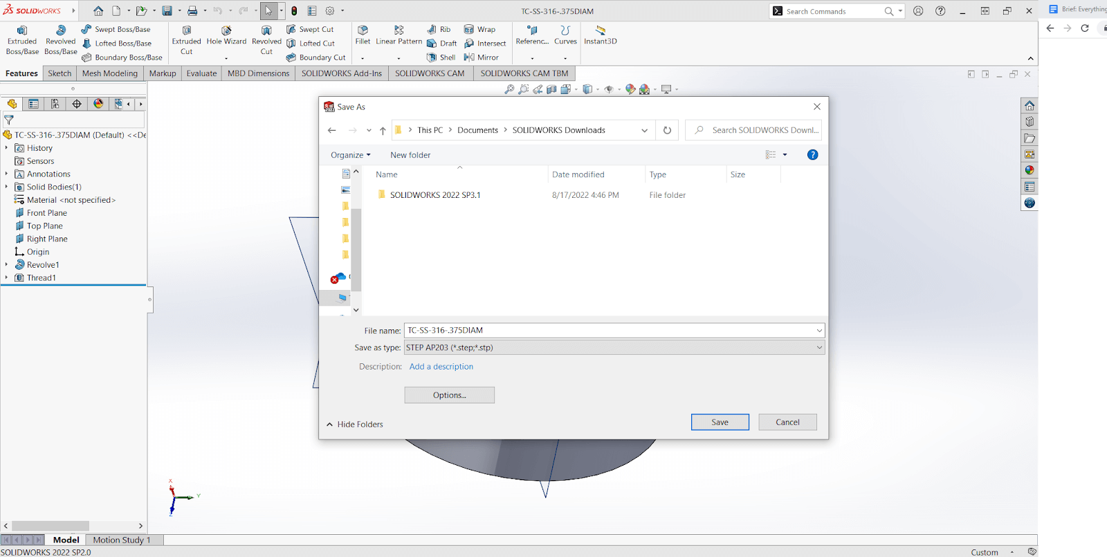
As an engineer, you probably have experience opening, reviewing, creating, or editing STEP files. During my freshman year at Rose-Hulman, I sat in a class with 30 other students who all seemed to have an enormous amount of knowledge about 3D modeling. Meanwhile, I had never created nor even opened one before, so the first time I tried to create a 3D CAD model in SOLIDWORKS — a simple cube with a hole in the middle — I was lost.
I hadn’t learned how to visualize things in 3D as my peers did, but that first exercise challenge instilled a passion for creating and helped me develop a knack for engineering drafting. Hopefully this article will kindle that same passion for creation in you!
CAD models are the backbone of any engineered product for any industry. They provide 3-dimensional geometric relationships, size, and shape, as well as portray the function of a part. There are many file types for 3D CAD models, but the STEP file format is commonly used because of its universal compatibility with a multitude of 3D modeling software. STEP files also read/save the entire body profile of a 3D CAD model and therefore provide a high level of accuracy.
Whether you are an engineering drafting professional, a college student in your first engineering graphic design class, or a mechanical engineer who wants to sound smart, read on to learn everything you need to know about STEP files!
STEP File Definition and History- What is a STEP File?
The file format that I used in that freshman engineering graphic design class is still commonly used today — the STEP file format. STEP stands for Standard for the Exchange of Product Data, and ISO (International Organization for Standardization) is the organization that created the STEP file in the 1980s.
The ISO TC 184 created the exchange format (aka exchange structure) for the data modeling language to be transferred between computer systems. This structure is laid out in the standard ISO 10303-21 (full name: STEP-file, ISO 10303-21 — Industrial automation systems and integration — Product data representation and exchange — Part 21: Implementation methods: Clear text encoding of the exchange structure).
STEP files were created to allow easy file sharing across different software programs through a standardized 3D model and design format. The first STEP file edition was released in 1994 and two more editions were released in 2002 and 2016.
According to the ISO standard, a STEP file has the following characteristics:
- STEP files consist of lines of characters that are sequences of records in ASCII format
- STEP files are highly precise formats for exchanging product data that conforms to a schema in the EXPRESS data modeling language (reference standard ISO 10303-11)
- STEP files contain (Unicode) code with the format of U+0020 to U+007E and U+0080 to U+10FFFF based on the hex chart of ISO 10646. Unicode is a character code language or encoding scheme with code points that are unique numbers for characters or symbols. The code is written as a ‘U’ then a + sign then a number in hex format (i.e. ‘0020’).

Why Does a STEP File Offer Unparalleled Precision?
The reason a STEP file can convey all the detail and body information for a 3D solid model — instead of the basic geometries conveyed with other file types — lies in the mathematical representation model from which a STEP file is built.
STEP files utilize a mathematical curve representation known as NURBS (Non-Uniform Rational B-Splines). NURBS are mathematical representations of 2D/3D objects. A NURBS model consists of many points connected by curves, as opposed to the polygon mesh of triangles used for FEA simulation.
NURBS approximation allows complex surfaces to be locally controlled so that kinks don’t develop across the spline. NURBS is also useful for constructing many types of complex surfaces in a 3D model because the curvature allows for a smooth, flexible, and minimal approach to model with higher accuracy.
Here is a list of the advantages of STEP files owed to the NURBS format:
- Simple and elegant curves allow for a variety of shape representations in 3D format
- Curves are smoothed and minimal
- Due to their simplicity, files are easy to share, customize, edit, and save
- Due to their simple construction, many free software programs can open and view STEP files

What Software Programs are Compatible with Opening, Creating, or Editing STEP Files?
Since STEP files are so popular, they are compatible with a wide variety of CAD software programs, including:
- Adobe 3D Reviewer
- All SOLIDWORKS software programs (Dassault Systemes CATIA also)
- AutoCAD
- FreeCAD
- ShareCAD
- STP Viewer
- IMSI TurboCAD
- Autodesk Fusion 360
- Pro/Engineer / Creo
- eDrawings (Opening and Viewing only)
- 3D Viewer Online (Opening and Viewing only)
- Autodesk Viewer
- Clara.io
- GOM Inspection Suite (this comes with a cool metrology package)
- Glovius STP Viewer
How to Open, Read, and Convert a STEP File
The links below detail how to open, read, edit, and convert STEP files with some commonly used software programs (see links in previous section for how to open with free STEP viewers):
What Else is a STEP File Known As?
Other names for a STEP file include:
- ISO 10303 File
- STP File
- .stp File
- P21 File
What is the Difference Between a STEP vs OBJ vs IGES vs STL File?
Here is a table which shows the main differences between the most common 3D CAD model types:
| File Acronym/Common Name | Filetype Name | Surface Definition Structure | Pros | Cons |
| STEP | Standard for the Exchange of Product Data | A series of curves, NURBS | Can store additional data like GD&T, materials, model intent; high accuracy due to curvature modeling | Can be large and suffer from small losses during spline encoding |
| OBJ | Object Files | Polygon mesh as a list of vertices joined by edges | More surface definition than STL files; more accurate definition than STL files, when considering same # of meshed polygons | Doesn’t provide a highly accurate portrayal of object’s geometry |
| IGES | Initial Graphics Exchange Specification | Similar model as STEP files but splines are converted to polygons | Can store units within file header; accurate surface modeling leads to high accuracy | Not compatible with as many programs as STEP files |
| STL | Stereolithography | A mesh of triangles, or tessellations | Lower file size | Doesn’t approximate surfaces as well as curves with STEP files |
Sourcing Simplified – Start Your Next Project With Fictiv
At Fictiv, we are here to help source all your custom manufactured parts using your carefully designed STEP files. Our CNC machining service can even create your parts in as little as 2 days!
Fictiv is your operating system for custom manufacturing that makes part procurement faster, easier, and more efficient. In other words, Fictiv lets engineers, like you, engineer. Create an account and upload your part to see what our instant quote process, design for manufacturability feedback, and intelligent platform can do for you.


