Time to read: 6 min
In earlier chapters of FictivMade, I walked through the detailed design process, DFM analysis, and how to kick off the tooling order. While placing the order is a big milestone, there is still more work to be done before the finish line.
Now comes the stage of the multi-tool phone stand project where the injection mold we designed and built finally gets put to the test. Mold trials—often called T0, T1, T2, T3—are a critical part of the injection molding process, giving manufacturers and engineers the chance to validate tooling, check part quality, and make necessary design and mold revisions before committing to full-scale production.
Thanks to Fictiv’s overseas manufacturing partners and our engineering team on the ground, we were able to identify issues early and make targeted adjustments. That proactive approach not only saved time and cost but also gave us the confidence that our mold was on track for production-ready performance.
Preparing the First Mold Trial (T1)
The T1 mold trial is where the injection mold runs for the first time under production-like conditions. The goal is to:
- Verify that the mold functions correctly (opening, closing, ejecting)
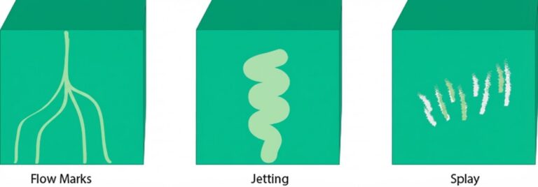
- Check part quality for cosmetic defects (sink marks, flash, flow lines)
- Measure critical dimensions to ensure design intent
- Assembly and functional testing of the parts
For the multi-tool phone stand, we injected PC/ABS material for the main body, TPU for the overmolded grip, and POM for the hinge pin. Our engineers paid special attention to product quality and functionality, which gave me a head start on validating and improving the parts myself.
Note: Manufacturers will often run what they call a T0 sample that precedes T1, as an internal test of the tool’s basic functionality. T1 is typically the first customer-facing sample.
T1 Results: Issues and Resolutions
While the overall part quality was strong for a first trial, our functional and visual inspections uncovered several defects and functional issues that needed attention:
1. Weld Lines
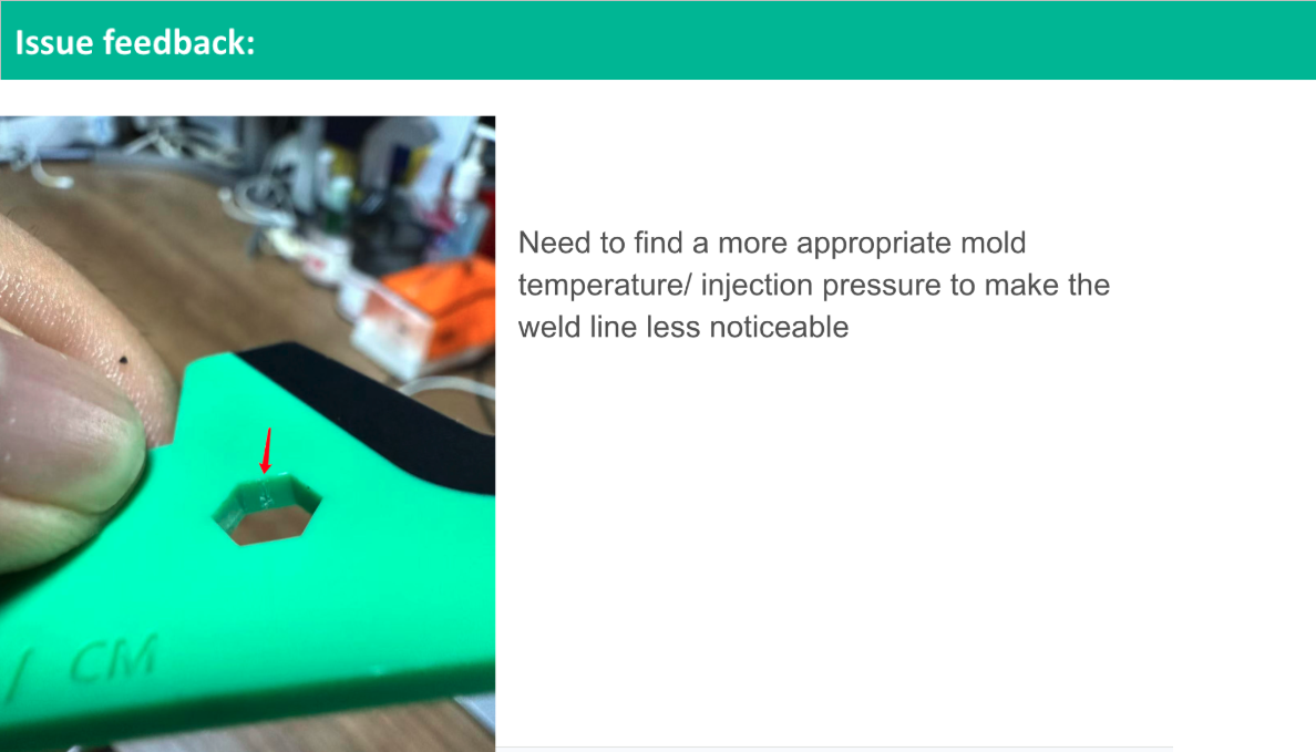
Visible lines were found in the hex recess area, as the DFM warned. These were caused by the steel that formed this feature, which blocked the flow path of the material and caused the divided path to meet on the other side. While they were mostly cosmetic, we adjusted the injection temperature and pressure to reduce visibility of the weld lines.

Quality inspection note and image showing weld lines
2. Ejector Pin Marks
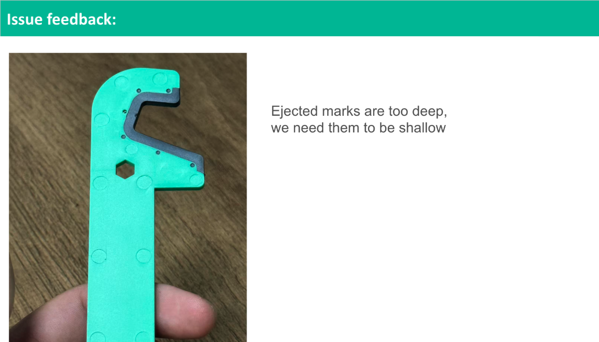
Several ejector pins left noticeable witness marks on cosmetic surfaces, as expected from the DFM. However, the marks were too deep and noticeable, which required adjustment.

3. Flash on TPU Overmold
The soft TPU overmold showed minor flash along the parting line where it met the PC/ABS substrate. The flash needed to be manually trimmed off, but we improved the clamping pressure and ensured a proper shut-off fit in the overmold tool to alleviate this issue.
4. Shrinkage on Thick Sections
Localized shrink was visible in areas of the TPU overmold. Our manufacturing partner was able to add a water line (cooling channel) in this area to encourage uniform cooling.
5. Hinge Looseness
The hinge rotated freely, but fit too loosely, which reduced product functionality and perceived quality. This was due to slight oversizing of the hinge bore and the intent of the design to allow for a steel-safe modification if necessary to tighten the fit.
I designed the hinge with clearance, in consideration of tolerances, to ensure that the parts would fit together across any variation outside of the nominal dimensions. This is usually a safer approach to tight-fitting components, because it’s easier and more cost-effective to add plastic by removing steel than the other way around.
Assembled product showing alignment shift due to hinge looseness
However, when the parts arrived, the fit was too loose. The hinge could be flexed open, and the pin could be disassembled too easily. It was a significant functional issue, but I had planned some ideas in advance about how to resolve it.
These issues were relayed to me by Alex Fu, TPM at our manufacturing partner in China, with whom I worked closely to resolve issues and coordinate the shipping of samples.
Image showing the flexibility and cored-out area of the original pin snap design
Collaboration With Engineers Overseas
One of the advantages of Fictiv’s global manufacturing network is the ability to collaborate with engineers on the factory floor, even when sourcing overseas:
- Photos & videos of the sample parts showed problem areas post-trial.
- Feedback from tooling engineers helped us pinpoint solutions before shipping.
- Collaborative decision-making allowed us to approve modifications quickly with feedback on the ground.
This overseas engineering feedback loop saved significant time and ensured the mold was improving with each iteration.
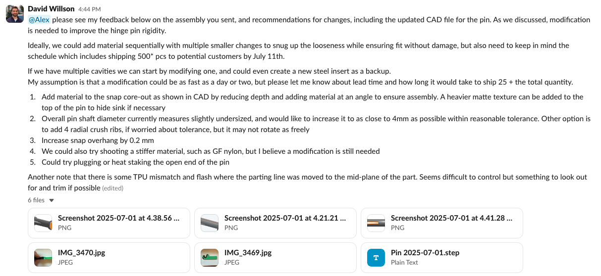
T1 Feedback from Cameron Moore, General Manager of Fictiv China
Mold Revisions After T1
The main mold revisions after T1 included:
- Reducing the hinge clearance in width and diameter for a snugger fit.
- Testing glass-filled nylon material for the pin to add rigidity.
- Running the tool hotter to reduce weld lines.
- Adjusting ejector pin heights to minimize marks.
- Tightening shut-offs in TPU overmold tool to prevent flash.
- Adding cooling line in TPU area to minimize shrink.
Most of these improvements were made on the manufacturing side by making adjustments to the tool. The only issue that necessitated a design and tooling change was for the hinge pin fit. Since it was steel-safe, the change was able to be put into effect fairly quickly.

T1 Hinge Design Changes
Using tolerance analysis and snap fit design best practices, I modified the pin and hinge section to be stiffer and tighter.
One part of the solution was increasing the diameter of the pin shaft to snug up the fit, but I also needed to make it hold in place more securely. I increased the snap overhang slightly, and added material to the cored-out inner area to stiffen the flanges. As you see in the image below, I added material at an angle so that the flanges could still flex with enough displacement to clear the through-hole during assembly. These changes would also make it slightly harder to assemble, which I had to be conscious of.
We also closed the gap between the “front” and “back” main parts by adding a slight amount of material with EDM, so that there would be less movement between them.
T2 Trial: Verifying the Fixes
The T2 mold trial confirmed that:
- The hinge was now robust enough and fit securely.
- Weld lines were significantly less visible.
- Ejector marks were minimal and acceptable.
- TPU overmold flash was eliminated or trimmed.
- Shrinkage was controlled, resulting in more uniform surfaces.
- Tick marks were added with laser engraving upon a recommendation from our General Manager of Fictiv China, Cameron.
First Article Inspection (FAI)
After each tool trial, parts are sampled and measured to make sure they meet specifications outlined in the documentation and files, such as 2D drawings. Metrology tools such as calipers and CMMs are used to take measurements which are then documented in a report that is provided to the designers.
Why Mold Trials and Revisions Matter
Skipping or rushing mold trials can lead to expensive problems during production. It’s essential to build time into your schedule for trials, as it is nearly impossible to have perfect parts on the first run. Sometimes manufacturers don’t even put final textures in the mold for the first trials in anticipation of potential changes that would require re-texturing.
By taking the time to run T1, T2, and subsequent mold trials, we:
- Prevented multiple defects from reaching mass production.
- Reduced the need for costly post-production rework.
- Built a mold that can run reliable, consistent parts for years.
Next Up in the FictivMade Series
In the next FictivMade segment, we’ll move into unboxing and review of final parts, followed by tooling sign-off for production! There’s nothing better than getting your product finalized, and I’m excited to share this next step.
Ready to Bring Your Design to Life?
Whether you’re in the early prototyping phase or preparing for high-volume production, Fictiv’s digital manufacturing platform gives you instant quoting, automated DFM feedback, and access to a global network of vetted suppliers.
From the first mold trial to final production, our experts help ensure your parts are manufacturable, cost-effective, and high quality—the first time and every time.
Get a quote today and see how we can accelerate your next project.


