

Time to read: 11 min
A crucial part of sheet metal fabrication is planning how the assembly will be welded into a complete unit, known as a weldment. An optimized design makes the weldment process more efficient and cost-effective, while also improving structural strength, reducing the risk of rework, and preventing issues like weak welds or cracking.
This guide will discuss:
- How to achieve a weld-friendly design
- Types of sheet metal welding
- Joint types
- Weld joint design
- Corner design
- Tabs and slots
- Drawing annotations
- Common mistakes and how to avoid them
- Cosmetic welding
- Fictiv sheet metal resources
Download the PDF version of this guide here.

Designing Sheet Metal for Weldability
Several key features should be considered to achieve a weld-friendly design, including:
- Matching the welding type to the material choice and thickness
- Selecting the type of joint
- Preparing corners
- Including tabs and slots, or cleco fasteners
- Effectively communicating decisions through 2D drawing annotations
Types of Sheet Metal Welding
There are a few common techniques for welding sheet metal. The type of welding that you intend to apply to your component will also influence the material selection for the project, or vice versa. These choices go hand in hand to deliver a high-quality product.

MIG Welding
Metal inert gas welding utilizes an inert gas over the consumable electrode to shield the melt pool from oxygen, thereby preventing the formation of oxidation products (impurities) that could compromise the weld’s strength. The inert gas is usually argon or carbon dioxide.
This process can be used to weld a wide range of simple materials and is relatively easy to perform. However, MIG should not usually be used on sheets thinner than 0.04 inches (1 mm), as there is a risk of the heat input causing burn-through or warping of the sheets.
TIG Welding
Tungsten inert gas welding uses a non-consumable tungsten electrode to generate the electric arc and can employ an additional filler rod. Inert gas is still used to shield the weld pool. TIG welding provides high-quality welds that are visually pleasing.
TIG welding is more frequently applied to more complex alloys and can weld sheets as thin as 0.012 inches (0.3 mm) if done with careful settings and by a skilled welder. Generally, it is only recommended for sheets of at least 0.02 inches (0.5 mm), depending on the material.
Spot Welding
Spot welding uses electrical resistance to heat the metal and form a weld. The sheets to be joined are clamped between two copper electrodes, and a high current is passed between the two electrodes and through the workpiece. The resistance of the sheet metal to this current flow causes heat and localized melting, and this forms a weld once the electrodes are removed.
The process is typically very fast (less than a second) and provides a small, neat weld with a minimal heat-affected zone. Spot welding is commonly used for materials such as carbon steel and can be applied to sheets of thickness from 0.02 inches (0.5 mm) to 0.09 inches (2.3 mm).
Joint Design for Optimal Welding
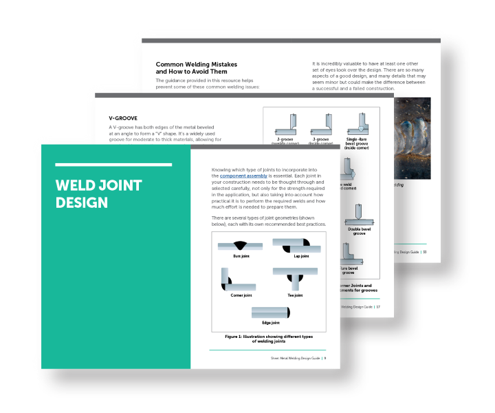
Knowing which type of joints to incorporate into the component assembly is essential. Each joint in your construction needs to be thought through and selected carefully, not only for the strength required in the application, but also taking into account how practical it is to perform the required welds and how much effort is needed to prepare them.
There are several types of joint geometries (shown below), each with its own recommended best practices.

Butt Joint
The two sheets are placed against each other edge-to-edge in the same plane, and a weld is run along the seam between them. The thickness of the sheets to be welded will dictate the preparation of the gap and whether a groove (bevel) shape between them is necessary for proper weld penetration. Thin sheets (3/16” or less) can be butt welded together with minimal preparation, as a single weld can achieve full penetration.
Lap Joint
Lap joints are not very common, as they are prone to bending. The ends of two metal sheets are overlapped, and a weld is run along the edge of the upper sheet (single lap) or the edges of both upper and lower sheets (double lap).
Corner Joint
The two sheets are joined at right angles, forming an L shape. This arrangement is common in box or frame constructions. These joints can be welded along the inside corner or the outside corner, and various types can be applied, such as fillet, bevel, J-groove, or edge welds (see Figure 2 below). Weld sequence and clamping are critical in order to avoid warping.
Tee Joint
These are used to join one sheet perpendicular to another sheet, and are welded along the intersection. There are many different approaches for these welds, including fillet, bevel, or J-groove welds. There is a common risk of tearing due to over-restraint if a continuous fillet weld is used. Designers should consider how to distribute the stresses in the joint, such as by using balanced double-sided welds instead of long single-sided welds.
Edge Joint
The two sheets are laid parallel to each other and welded along the outer edge. This method is more frequently applied to thinner sheets, as it can reinforce the edges.
Choosing the Right Weld Joint
The type of weld joint you select and design for depends on functional requirements such as load direction, access for welding, aesthetics, and fit. For example, if a component must fit precisely within another part or maintain a clean outer surface, an inside corner weld (also known as a fillet weld on the internal face) may be preferred to keep the exterior flush.

1. Design and Structural Requirements
- Evaluate the type of loads (shear, tensile, bending) the joint will experience.
- Consider the sheet thickness and how it impacts joint type and weld penetration.
- Assess whether the joint can be accessed for welding from one or both sides.
2. Cost Considerations
- Factor in the cost of the welding process (manual, robotic, spot, laser, etc.).
- Consider the need for joint preparation, fixturing, and alignment.
- Account for any required post-weld operations like grinding or finishing.
3. Durability and Application-Specific Needs
- Address corrosion resistance and sealing needs for the operating environment.
- Design for fatigue resistance and load cycling if applicable.
- Factor in aesthetic requirements if the weld is visible in the final product.
4. Material Type and Compatibility
- Consider the weldability of different metals (e.g., aluminum vs. steel).
- Prepare for special requirements with coated or dissimilar materials.
Types of Grooves for Sheet Metal Welding
Grooves are helpful features in sheet metal welding that enable proper weld penetration and joint strength. Depending on the welding application, material thickness, and desired weld quality, different groove types may be used to prepare the joint edges.
Here are four common groove types:
1. U-Groove
A U-groove has a rounded bottom, resembling the shape of the letter “U.” It is often used in thicker materials to allow for deep weld penetration with less filler material compared to square grooves. This type provides a strong joint while reducing the amount of welding required.
2. J-Groove
The J-groove features a curved edge on one side and a flat edge on the other, forming a shape similar to the letter “J.” It is typically used for one-sided welding, especially when only one part of the joint is beveled to conserve material and labor.
3. V-Groove
A V-groove has both edges of the metal beveled at an angle to form a “V” shape. It’s a widely used groove for moderate to thick materials, allowing for good weld penetration and ease of access for the welding arc.
4. Bevel-Groove
The bevel-groove involves beveling only one edge of the joint, as opposed to both in a V-groove. It’s ideal for applications where one side is more accessible or where welding from only one direction is necessary.

Designing Corners for Welding
High-quality sheet metal assemblies must be designed with corners that can be easily fitted for welding. Corners create stress concentrations, so it is necessary to design them using techniques that minimize these stresses. There are options for edge treatments that can be applied so that when corners are assembled, they are easily weldable and reduce stress.
These edge treatments are typically either chamfered or radiused. Edge treatments achieve the following:
- Smooth and safe edges of the sheet metal (improving personnel safety while handling)
- Providing clearance for bending and assembly
- Preparing the edges for neat and effective welds
Chamfers or bevels can be machined at a range of angles (such as 45°, 60°, or 82°) according to the welding needs. Bevels improve the penetration and strength of the weld. Unfortunately, the machining does add to the fabrication cost.
Radiused edges are easier and less costly to produce because they can be formed by simple bending, whereas chamfers usually require additional machining.
Relief cuts are small cuts or notches close to bending lines that avoid deformation or warping during bending. Relief cuts enable sharper bends and better fit-up where two bends intersect or where bends meet flat surfaces. It is essential to incorporate these kinds of elements into the design of sheet metal corners to achieve accurate fabrication and high-quality corners with neat and strong welds.
These elements, when designed into the sheet metal, allow corners to be formed with minimal stresses and to be quickly welded.

CAD software, such as SolidWorks, offers various options for corner treatments and gap size when converting to sheet metal.

You can then add a weldment feature to fill the corner relief and edge gap, and show or suppress it in your 2D drawings.

Incorporating Tabs, Slots, and Cleco Fasteners into Sheet Metal
Modern precision in laser cutting of sheet metal has fuelled the use of tabs and slots for self-fixturing. This brings numerous advantages over traditional sheet metal assemblies:
- Higher alignment accuracy
- Quicker assembly
- Minimal additional fixtures are required
- Lower assembly costs
However, incorporating tabs and slots into your design needs to be done carefully, with an appreciation for the stress concentrations and weaknesses that they may introduce. Slots are an obvious example, as the material removed can weaken the part, but tabs can also cause stress concentrations where they meet the main sheet. In both cases, it’s best practice to avoid sharp corners that will increase stress concentrations.

When designing tabs and slots, it’s important to follow guidelines for material thickness, part size, and clearances to prevent warping or cracking. For instance:
- A good rule of thumb is to provide a minimum clearance of 0.05 to 0.01 inches between mating faces.
- Dogbone holes (small radius holes) at the corners of slots are a great approach to limiting stress concentrations when tight clearances are required.
- Other techniques, such as tapered tabs or short tabs with the use of plug welds, can also limit the risk of cracking.
A similar consideration is the inclusion of Cleco holes for temporary fastening, particularly for sheets that will be used for aluminum aircraft bodies. This step in the design phase can allow for flexibility in welding methods based on capacity and available equipment.

Annotating Welds in 2D Drawings
Once your sheet metal design is finalized with weldability and assembly in mind, ensure all details are clearly documented and conveyed to the fabricators through precise drawings.
There is a system of standard symbols and callouts from the American Welding Society (AWS) that should be added to a technical drawing for this particular purpose. These symbols are shown in Figure 6 below.
Each symbol comprises several components, such as the reference line, arrow, tail, weld symbol, and supplementary annotations. Each element carries some of the necessary information for the weld, and it is best to specify each detail precisely. It’s helpful to have a review of the completed annotated drawing(s) to confirm readability and reduce errors.

Common Welding Mistakes and How to Avoid Them
The guidance provided in this resource helps prevent some of these common welding issues:
- Burn-through
- Warping
- Cold welds
- Porosity
Metal welding can fail when using sheets that are too thin for the welding method, resulting in burn-through or warping. Burn-through can also occur if the amperage is set too high during welding or if too large an electrode is used.
Completed welding can also have various defects, such as cold welds or porosity. Cold welds occur when there is too little heat input, and the metal does not fully melt, resulting in incomplete fusion. Porosity occurs when gas bubbles are trapped within the weld, weakening the joint. The cause of this porosity can be poor shielding or contamination of the base metal. It is important to complete a trial run to optimize these welding settings, with proper inspection, testing, and quality control after welding to ensure that the fabrication is being completed successfully.
It is incredibly valuable to have at least one other set of eyes look over the design. There are so many aspects of a good design, and many details that may seem minor but could make the difference between a successful and a failed construction.

Cosmetic Welding in Sheet Metal Fabrication
Cosmetic welding refers to welding processes that prioritize visual appearance alongside structural integrity. It’s commonly used in applications where the welds are exposed and aesthetics are critical—such as in consumer products, automotive panels, appliances, and architectural components. The goal is to create clean, smooth, and minimally visible welds that require little to no post-processing like grinding or sanding.
Cosmetic welds are typically achieved using techniques such as TIG (Tungsten Inert Gas) welding, laser welding, or controlled MIG (Metal Inert Gas) welding, depending on the material and design requirements. These methods enable precise control of heat input and bead profile, helping to avoid common cosmetic flaws such as spatter, burn-through, or excessive discoloration.
Sheet Metal Weld Classes
In sheet metal fabrication, cosmetic weld finishes are often categorized into classes (A, B, or C) based on their visual appearance and post-processing requirements. Clear communication of weld class during design and quoting, fabrication, and quality inspection helps align cosmetic expectations with manufacturability and cost.
• Class A (High Aesthetic):
Designed for highly visible surfaces (e.g., consumer products, medical devices, or architectural finishes). Welds must be uniform, smooth, free of spatter or discoloration, and often require no additional grinding or finishing. Commonly used with stainless steel or aluminum TIG welds.
• Class B (Moderate Aesthetic):
Used when welds may be visible but are less critical to final appearance (e.g., interior frames or hidden assemblies in appliances). Some minor post-processing may be acceptable, such as blending or light sanding.
• Class C (Non-Cosmetic / Structural Only):
Focused purely on strength and function, with no aesthetic requirements. Visual flaws, such as undercutting or discoloration, may be acceptable as long as the weld meets the mechanical specifications.
These classifications are particularly important when working with aluminum and stainless steel, as both materials can be more prone to heat-related discoloration or warping than carbon steel.

Smarter Sheet Metal Designs with Fictiv Resources
A great deal of thought goes into creating an efficient sheet metal design. In particular, we’ve covered the various aspects that are important for creating a weld-friendly design that allows quick, reliable, and cost-effective fabrication.
To optimize each of these elements, collaboration between the design team and the fabrication team is extremely valuable. Seemingly small changes can yield significant results in terms of efficiency and cost savings. Fictiv has a global team of experts with boots on the ground that can help facilitate efficient communication.
Since there is much more to cover in the field of sheet metal fabrication, you may want to delve deeper with some of these additional resources and tools:
- Sheet Metal Design Guide eBook
- Sheet Metal Manufacturing Guide eBook
- Sheet Metal Prototyping
- All About Sheet Metal
Ready to get started on your sheet metal project? Get a quote today.