Time to read: 6 min
If you’re involved in the operation and maintenance of a manufacturing facility, chances are that you need to procure Maintenance, Repair, and Overhaul Parts (MRO) from time to time. In the past, you may have spent hours measuring minute details to create a drawing or solid model of the component you are hoping to replace.
Now, reverse engineering is a bit easier. New 3D scanning technology has eliminated the need for hand measurements (sometimes known as CAD scanners or CNC scanners). This reduces measurement inconsistencies, speeds up the process, and gets you to the fun part, CNC machining components. So, it’s time to put down your calipers and up your reverse engineering game with our best tips for utilizing this incredibly useful technology.

How Does 3D Scanning Work?
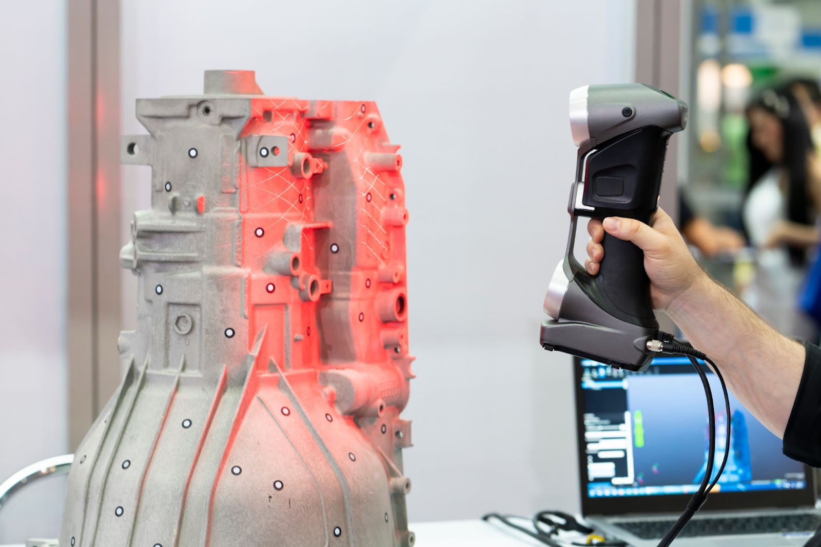
3D scanning uses lasers or structured light to digitally recreate a part’s surface in a non-contact, non-destructive way. This is beneficial for the maintenance and overhaul parts because it provides you with an exact replica of the part you need to replace. And knowing how the scanning process works is foundational for ensuring you use the technology correctly and to its full potential.
The result of both 3D laser and 3D structured light scanning is a massive dataset in the form of high-density point cloud measurements. These datasets are similar to what you achieve with finite element analysis (FEA) meshing with the triangulation method.
3D laser scanning technology uses a projected laser line on the surface of the part and sensor cameras to record the changing distance from the camera to the part’s surface (laser length) and the shape of the laser line (contour at the surface of the part). The resulting data provides XYZ coordinates utilizing the triangulation method in the same way 3DLS technology does, but laser scanning isn’t considered to be as accurate.
3D Structured Light Scanning (3DLS) is performed by two digital cameras that record data from a part that has a digital projector and LED light projecting a pattern across the part’s surface. The light that is projected is of the blue wavelength and the cameras capture data by a triangulation method which provides high levels of accuracy. The LED light fringe allows for higher levels of precision because the cameras can detect depth, shape, as well as the contrast of the light. It all adds a level of precision not found with 3D laser scanning to ensure your MRO parts are as precise as possible.
3D Scanning Machine Mounting Types
There are three commonly utilized mounting techniques for 3D scanning equipment:
- Tripod mounted: uses a stationary camera system mounted on a tripod and moves across the field of view capturing data with lasers (often for larger MRO parts or critical parts)
- Handheld: a human holds the scanner and moves around to capture the part (often for smaller parts or those that don’t require as much precision)
- CMM gantry style: the 3D scanner is mounted to a robotic arm or a CMM gantry where it is positioned over the part to be measured
How Does a Computer Convert Point Cloud to a Useful File Type?
So, how does the point cloud of measurements convert to a solid model that you can have manufactured for an MRO replacement? Well, let’s first start with the definition of a point cloud of measurements:
- Point clouds are datasets that represent points in space
- The points define the cartesian (XYZ) geometric coordinates of a unique, single location; some points contain color or vector information as well
- The individual points are stitched together in a process called registration
So, a scanner and processor work to collect the data from the scans in a highly-dense point cloud format. The density of the points is directly proportional to the detail of the resulting solid model. Unlike other data types, point clouds can be processed with open source software, Point Cloud Library (PCL) which is a standalone and free software.
The PCL software utilizes a set of algorithms for filtering, estimating features, the registration process, and surface reconstruction to convert the data set into a polygon mesh. For more technical information on PCL or the process, check out the PCL website.
This process utilizes a Non-Uniform Rational Basis Spline (NURBS), a mathematical model that approximates and displays curves and surfaces, to display the polygon mesh — similar to how FEA displays meshes. Common point cloud formats are ASCII, Binary, LAS, PTS, PTX, XYZ, LAZ, SDF, PLY, and Fast Binary. Unfortunately, not all file formats are compatible with all software types, so check what works with your software before selecting a file type.
Typically, point cloud data should be filtered down to only the necessary points prior to exporting. The rule of thumb is to filter down to less than a million points to reduce the amount of time it takes to perform the file conversion. From there, you utilize software to convert the point cloud data to a usable file.
Different software uses different techniques to treat the triangulation for a mesh output. The mesh output provides computed triangulations of the surfaces, allows for some of the rigidity of features to remain intact, and provides close approximation for surface contour. When building meshes, you can play around with the polygon count and density, which have an impact on surface resolution and accuracy. Common (CAD) export file types include: DXF, E57 (per ASTM E 2807-11), IGES, DAE, 3MF, and PLY.
How to Prepare a Part for 3D Scanning
Now that you have a good grasp of how 3D scanning works, it is time to talk about optimizing your 3D scanning process from setup to finish. Optimizing the environment and scan settings is critical to ensure you obtain the most accurate geometry of the surface of the MRO part you’re scanning.
And getting the highest quality raw scan possible is critical because the quality of the resulting solid model — and therefore the quality of the final part — is greatly dependent on the raw scan. There isn’t much you can do to fix a scan quality issue after the fact.
So, let’s discuss how to get a great scan with the proper setup:
- Ensure the part you are scanning is rigidly controlled during scanning. For example, if you’re scanning a light part, secure it tightly to a surface or place it in a room with decreased airflow.
- Ensure there aren’t stray vibrations from sound or other sources that can move the part while the scanner is collecting point cloud data.
- Control your part’s shine. Scanning an object that projects light is going to result in refracted or reflected laser and light beams. This disrupts your measurements because the scanner won’t correctly collect measurements in these areas. (Pro-tip: Apply a developer aerosol spray coating to shiny surfaces prior to scanning, and make sure it is completely dry as well.)
- Set up your scanning environment with a dark background and limit (if any) light entering the area. You can even use black paper or black fabric for a backdrop. Use as dim lighting as possible to limit interference.
- Ensure your equipment is in good working order and properly calibrated. Scanning equipment has a tolerance associated with it; without proper calibration, you can’t get accurate scans. Check your equipment’s manual or technical data sheet to determine if the manufacture must perform the calibration.

There are also ways to enhance the quality of the 3D scan with modifications during scanning:
- Use built-in feedback (and your experience) to select the correct scan settings to get the highest quality point cloud data. Ask yourself: Is the exposure too high? Does the brightness need to be adjusted to compensate for the environment? Then, do a trial scan and make adjustments accordingly.
- Most objects will require you to stitch together data from multiple scans from different orientations to ensure you have captured the entire surface of the part. Use a rotating table — even a simple cake-turning table or lazy susan — to rotate the part while you are performing your scans. This allows you to turn your part a set number of degrees for each scan to ensure smooth and complete coverage. Motorized rotary tables make the capture process even smoother and really pay off if you’re scanning multiple parts. Look around your machine shop, you may have a machine that can rotate your part for you!
- Try to maintain a consistent distance between the scanning equipment and the MRO part you’re scanning, and keep the scanning equipment steady. Vibrations act as noise in the scan and disrupt the outcome of the solid model of the MRO part.
Sourcing Simplified – Start Your Next Project With Fictiv
With Fictiv, thousands of companies have rapidly built and replaced production-line tools and parts with a cost-efficient maintenance, repair and operations strategy. Fictiv is your operating system for MRO manufacturing that makes part procurement faster, easier, and more efficient. In other words, Fictiv lets engineers, like you, engineer. Create an account and upload your part to see what our instant quote process, design for manufacturability feedback, and intelligent platform can do for you.


