Time to read: 7 min
The ultimate goal of DFM (Designing for Manufacturing) for CNC machining is to design parts that achieve the design requirements while reducing the complexity of machining operations and the potential for quality issues. When designing for CNC machining, the maxim, simplicity is the ultimate form of sophistication, applies.
Despite its automated nature, CNC machining can still be an expensive process that’s even more expensive with large production runs — where complex features and convoluted designs will result in significantly higher costs. In some cases, however, complex parts are required, so the goal is to limit manufacturing complexity as much as possible. This article will explore some common design tips, the elements to include in a technical drawing, and how to prepare a model for CNC machining in order to simplify the manufacturing process.

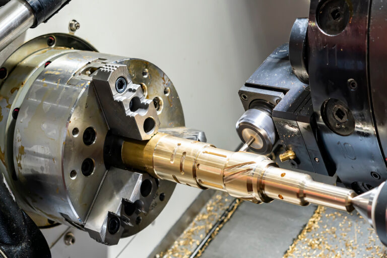
Figure 1: Milling Head
CAD Design for CNC Machining
Designing parts for CNC machining can seem daunting because there are many variables to keep in mind. Designing parts without considering how they will be machined is a good way to create excess costs, and if the parts cannot be machined, they must be redesigned. Either way, you should design parts with CNC machining in mind from the start. Listed below are some key considerations for improving your CAD designs for CNC machining:
Use the Right Software
When designing parts for CNC machining, it’s best to use 3D modeling packages like SolidWorks®, Inventor®, NX™, or Solid Edge®. These packages have many different features to streamline the CNC design process. Most also have optional CNC machining add-ons that allow seamless transitions from CAD (Computer-Aided Design) to CNC without the need to convert the file into a different file format. 2D CAD packages (like AutoCAD®) can be used to create designs for CNC machining, but doing so isn’t the most optimal method. Also, some CNC CAM (Computer-Aided Manufacturing) packages have limited 3D modeling capabilities only suited for simple designs.
Use Standard Tooling
When adding features to a design, it is important to be cognizant of the standard tooling available. Designing a part with features that coincide with standard tool sizes makes it easier to program the part and reduce machining times — for example, making internal fillets with a radius equal to a standard ball nose mill or holes with a diameter equal to standard drill sizes. Also, it’s advisable to only utilize standard threads as these typically require readily available, standard tooling.
Use Standard Material Sizes
It’s good practice to keep an updated list of common material stock sizes for reference. To reduce machining times and costs, CAD designs should be made within the constraints of common stock sizes.
For example, let’s say you want to design a shaft with an outer diameter of 31 mm. While 31 mm may be the optimal thickness for a specific application, it’s not the best for manufacturability, since the closest common size could be 40 mm. This means that 9 mm must be machined off the shaft to reach the final dimensions. Instead, design the shaft to have an outer diameter of 29 mm so that a standard 30 mm rod can be used and machined at a lower cost. In most cases, the thinner shaft will still meet your design requirements, and, if not, a simple material grade change can bring it back within the required parameters.
Reduce the Number of Fixturing Setups
Another important factor when designing for CNC machining is reducing the required fixture setups. A setup refers to placing the raw material (or partially machined material) in a clamping device so that the cutting tools can machine the relevant features. In some cases, the tool cannot reach where it needs to in order to create some features. For example, on a 3-axis CNC machine, the tool cannot drill a hole whose axis is parallel to the machine bed. In this case, the partially-machined part must be re-fixtured, which is time-consuming, may require additional fixtures, and adds cost. Whenever possible, design parts to reduce the number of times they must be repositioned.
Tool Reach
When designing deep pockets, it is important to understand that the deeper a hole, the more difficult it will be to maintain machining accuracy. Also, it may not even be possible for the tool to machine certain features — the chuck or collet may collide with the raw material. It can be difficult to know what these limitations are during the design phase, but in general, don’t design deep, narrow features unless necessary, and keep the depth:diameter ratio less than 10:1.

Tolerances
It is important to understand when to add tolerances to a feature and when not to. Over-tolerancing a part can result in significant additional cost because the machinist needs to set up machining operations more carefully for tight tolerances, which requires increased programming and machining time. Plus, after machining, these features must be measured to ensure the tolerances are met. If every feature is toleranced, it’s difficult for machinists to meet all the requirements and a higher scrap rate is likely. Tolerances are typically only required on features that need to mate with high-precision parts — like bearing grooves or where other machined parts mate together.
Pro-Tip: Check out our Visual Guide to GD&T for a refresher on drawing components, dimensioning, datum reference framework, and geometric tolerances.

Surface Finishes
Cosmetic surface finishes may improve how the part looks, but in most cases, they’re not required because the part may be hidden inside a larger assembly. Surface finishing on a CNC machine is a time-consuming and expensive process. A standard machining surface roughness of 63 µin or 1.6 µm is generally good enough for the majority of applications. Learn more about surface finishing of CNC-machined parts here.Fillets
Filets are generally used to reduce stress concentrations on parts and increase their fatigue life. Fillets can either be internal (concave) or external (convex). Internal fillets are often created by default due to the shape of the tool, like when a ball end mill is used. However, external fillets must be 3D profiled, which is a time-consuming operation. While you do need to break sharp edges, adding specific fillets purely for aesthetic purposes is often not worth the additional cost. An alternative, like a chamfer, may be better than a fillet because it can be machined in one operation and doesn’t require 3D profiling — you can also include an instruction on the drawing to break sharp edges and avoid additional requirements altogether.

Avoid Sharp Internal Corners
Sharp internal corners are, in most cases, not possible or difficult to achieve in CNC machining. This is because the tool is cylindrical and will always leave a rounded corner when cutting out a slot or groove. If a square part needs to mate into a square hole, then other techniques — like drilling relief holes in the corners — can help maintain the squareness of the feature.Avoid Deep Features
Deep features need longer tools to reach the bottom of the hole without crashing the chuck or collet. As the depth increases, the side load on the tool increases due to a moment force created by the cutting load. The tool then deflects and can either break or produce a poor machining surface due to chatter. Deep holes are easier to machine than deep slots since cutting holes only produces an axial load on the tool instead of an axial and a side load.
Manufacturing Drawing
Some machine shops require not only a CAD file but also a technical drawing for a part. A drawing is used to indicate features that are not clear on the CAD model; these features include hole callouts, surface roughness requirements, tolerances, and special instructions. A good technical drawing will supplement the CAD file and ensure that the machinist has all the information necessary to machine the part to the required specifications.
Alternatively, systems like MBD (Model-Based Definition) are used to indicate the features typically represented on a 2D drawing directly onto a 3D model. CNC operators can then view the model from different angles to see all the features, their tolerances, and any special notes. MBD is a powerful feature that is present in most CAD software, but in most cases, machinists still prefer technical drawing prints.

Preparing the CAD File for CNC Machining
Once your CAD design is complete, it can be prepared for CNC machining. In most cases, a neutral CAD format like a step (.stp) file is required. Native CNC file formats from popular CAD packages like Solidworks® and Inventor® can be directly imported in some cases, but it’s better to confirm which file format you need with the company doing the machining. Exporting a file for CNC machining is simple and doesn’t require any special steps. However, there are three different step formats to choose from, namely AP203, AP214, and AP242:
- AP203: This is the most general step format and contains geometric data and some limited model data such as approval status and security classification.
- AP214: This format has the features of AP203 but includes colors, GD&T (Geometric Dimensioning and Tolerancing), annotations, and tolerance data.
- AP242: This format includes PMI (Product Manufacturing Information) and is used when a model must retain MBD (Model-based Definition) annotations and notes.
In most cases, AP214 and AP242 are ideal for CNC machining. AP242 should only be used if implementing MBD functionality. In addition to the step file, a technical drawing is also needed to confirm dimensions, features, and special requirements.
Once the file is prepared, it can be imported into any CAM software package — then CNC programmers convert the CAD file into a set of instructions (typically referred to as G-code) for the CNC machine to follow.
Demystifying CNC Machining with Fictiv
You can see the effect various features will have on the cost of your CNC machined part by creating your free Fictiv account and requesting an instant CNC machining quote. Not only will this help you understand the implications of various design decisions, but it also gives you access to Fictiv’s team of experts who can guide you to the optimal design and have the part manufactured to your specifications at the click of a button.
So, upload your design today to see what our instant quote process, DFM feedback, and intelligent platform can do for you — we deliver complex parts at ridiculous speeds!