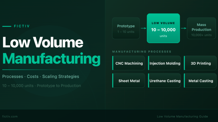
Time to read: 6 min
More than 3.2 million product designers and engineers use SOLIDWORKS worldwide. Fun fact: SOLIDWORKS crashed on me during a final exam once and my professor was not sympathetic — instead he decided to teach me a lesson in saving files more frequently. That lesson still haunts me over a decade later.
Pro-tip: Always follow SOLIDWORKS best practices. Don’t be like me and lose your data, enable autosave for your design files today!
Considering how many of us are out here using SOLIDWORKS and my desire to help others learn from my mistakes, I thought I’d share a few tips and tricks to help you become a SOLIDWORKS pro.
Note: The purpose of this article is NOT to convince you to use SOLIDWORKS over the other options that are out there. This article is for people that have already chosen SOLIDWORKS (or had SOLIDWORKS chosen for them) and want to improve their skills.
Customize Your Toolbar

SOLIDWORKS Command Manager
The Command Manager, shown above, is touted by Dassault Systèmes (the maker of SOLIDWORKS) as a simple and easy-to-use location for all the features, sketch tools and evaluation tools that a designer might need.
But simply put, it’s for n00bs. If you want to become a SOLIDWORKS pro, consider ditching the Command Manager in favor of a comprehensive and customized toolbar setup. It’s the quickest and easiest upgrade you can make.
Here’s an example of such a setup with a brief explanation:

As you can see in the picture, the 3D model is surrounded by about 200 SOLIDWORKS icons, that can each be used via a single click. Many of these features cannot be found in the Command Manager. For those that are in the Command Manager, such features require multiple clicks to use.
Switching to a custom setup like the example above can save you hundreds of clicks per hour! I know, it used to be that you couldn’t sacrifice so much screen real estate for commands. However, with large, hi-res screens, you still have plenty of space for your 3D model and the feature tree itself.
Use a Maximum of 3 Points per Spline
A spline in SOLIDWORKS is a method for creating complex or non-uniform curves — they’re either B-splines or style splines (Bézier curves). Splines are great for creating organic shapes while keeping good control over the results. However, too much control can negatively affect results as much as too little control.
The end points of a spline control the curvature constraints, while the through points of a spline dictate the weight and direction of the tangency of the localized curvature. As a general rule, try to use as few spline points as possible to achieve the desired result. I keep all of my splines limited to 3 points (both ends plus ONE control point somewhere in between).
SOLIDWORKS lets you add as many control points as you want to, but I don’t recommend it. Adding more than one control point tends to over-control the spline when using features such as lofts and sweeps, which yields undesirable waviness or ripples in the resulting surface(s).
The picture below shows what happens to a spline as you add more constraints or controls to it. As you can see, not enough constraints yields an undefined spline. On the other hand, too many constraints will make the spline appear more jagged, and those jagged transitions cause undesirable waviness and ripples.Pro-Tip: Check out this SOLIDWORKS help center article to learn more about deleting excessive spline points.

Trim, But Do Not Extend Spline Surfaces
As a general rule of thumb, spline surfaces can be trimmed as much as you want, but should not be extended past their original boundaries.
In reality, SOLIDWORKS lets you do both, but extending a spline-shaped surface involves SOLIDWORKS doing a lot of math to estimate what the spline-shaped surface would look like if it was created as a longer spline trimmed to the current spline — and keep in mind that the math is complex and the results are not so accurate.
When creating a spline-shaped surface, it’s a good idea to draw splines much longer than you think they need to be, do your chosen command using that longer spline, then trim the end result. Note, I am NOT saying to trim the original spline drawn in the sketch itself. You should trim the end result created using a longer spline. For trimming splines within sketches, see the next section below.

Use the Master Sketch Method to Trim Splines within a Sketch
Imagine a collection of splines that cross each other and you want to trim them together. Trimming these splines in a single sketch will automatically change the endpoints of those splines to where you trim them. This changes the way that the splines themselves are controlled/constrained because they are controlled by their endpoints, which are now different. This might not be what you intended.
Here’s an example: Let’s say you want to add a recess for your company logo on your product. You want the recess to be a diamond shape, but you want the sides of the diamond to be somewhat curved. In fact, you want the sides of the diamond to be curved in relation to other aesthetic elements in your product. So, you draw a collection of fully editable splines as shown below:

If you can tell from the image above, the original splines were set to tangent to geometry in the part itself. If you trim the splines so that only the curved diamond shape is left, the result is the same curved diamond, but the control points have moved to the corners of that diamond, as shown below.

Once you trimmed these splines together, you lost the method you used to control the shape itself. At that point, you would just be eyeballing any changes to the splines and hoping the results look good.The solution to this problem is something I call the Master Sketch Method:
Step 1
Draw as much content as you want in a single sketch. Don’t worry about trimming lines or splines. Instead, leave them all their original length. Call this sketch your “Master Sketch”.
Step 2
Create a new sketch on the same plane (or a parallel one) and use the convert entities SOLIDWORKS tool to convert some or all of the items in the Master Sketch into your new sketch. Call this new sketch your “Trimmed Sketch”.
Step 3
In the Trimmed Sketch, trim the converted entities from Step 2. Use this trimmed sketch for whatever feature you want.
Result
Your Master Sketch will be exactly how you originally drew it. Your Trimmed Sketch will be a trimmed version of the Master Sketch. Editing the Master Sketch will update the Trimmed Sketch, but the constraints intended for the splines are left intact.

Quick FAQs – Spline Sketches
- The Master Sketch method can be used for as many Trimmed Sketches as you want (maybe different variations of trimming the splines together).
- Editing the Master Sketch’s existing entities yields no rebuild issues unless you add or delete geometry from the Master Sketch.
- If you delete entities in your Master Sketch, the Trimmed Sketches will show those deleted entities as dangling. You can simply delete those entities from the Trimmed Sketches as well.
- If you add entities to the Master Sketch, it will update the Trimmed Sketches properly ONLY if you converted the entire Master Sketch at once. If you picked and chose what to convert and what not to, then your Trimmed Sketch will not automatically add the geometry you added to the Master Sketch. In that case, you can edit the Trimmed Sketch and use the Convert Entities tool to re-add the missing geometry from the Master Sketch.
Main Takeaways
SOLIDWORKS is a great tool for taking your ideas and turning them into digital 3D models that are ready for prototyping and production. Becoming familiar with the software’s lesser-known abilities and limitations, such as the ones shown here, will help you take your ideas farther, and faster. Good luck out there!
If you found this article interesting and are looking to learn more, check out How to Get the Most out of Surfacing in SOLIDWORKS, and this helpful SOLIDWORKS Training Manual.
Sourcing Simplified – Start Your Next Project With Fictiv
For all your custom 3D printed and CNC machined part manufacturing and finishing needs, Fictiv has you covered. We’re experts at producing custom mechanical parts in a variety of materials, and we simplify custom part sourcing with intelligent, streamlined, automated workflows. Fictiv is your operating system for custom manufacturing that makes part procurement faster, easier, and more efficient. Create an account and upload your part to see what our instant quote process, design for manufacturability feedback, and intelligent platform can do for you. Our 3D printing service can create your parts in as little as 24 hours, and our CNC machining service manufactures parts in as fast as 2 days!