Time to read: 6 min
This article was revised by Tessa Axsom in September 2023
Even in 2023, with the rising popularity of model-based definitions, engineering drawings are still a great way to communicate design intent for CNC machined parts that require tight tolerances, material specifications, or other special requirements. That’s why many Fictiv customers in the robotics, aerospace, automotive, and medical device industries attach drawings to their solid models when uploading to our platform.
Even with the importance of manufacturing drawings, not all engineers receive comprehensive training on creating great drawings that manufacturers can easily understand. This leads to non-standard formatting and over-tolerancing, which negatively impacts lead times, part cost, and clarity around specifications.
The following nine tips will teach you how to create better technical drawings that communicate your critical requirements and you save time and money. For step-by-step guidance on how to create an engineering drawing, check out How To Make a Great Engineering Drawing Manufacturers Will Understand.
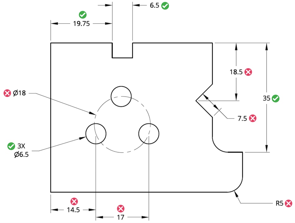
Tip #1: Dimension Only Critical and Measurable Features
In CNC machining, all dimensions can be derived from the 3D model. Therefore, you need only specify where threads are needed and dimensions for critical inspection on a 2D drawing. If you only have threaded holes to call out, you can skip the drawing and use Fictiv’s Auto Thread Detection tool.

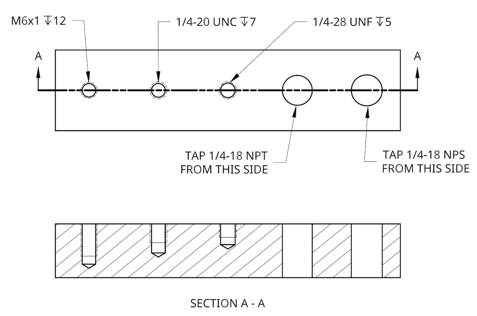
Tip #2: Communicate Hole Tapping Needs for Threaded Fasteners
Surprisingly, tapped hole specifications for future threaded fastener installation can be complex. So, make sure you’re utilizing the correct thread size and shape callout per the type of thread pattern you desire (i.e., ACME, UNC, UNF, or MJ). It’s also advisable to utilize a known thread specification for best results.
Pro-Tip: For more information on how to specify threaded holes on an engineering drawing, check out: Methods for Manufacturing and Calling Out Threaded Holes.

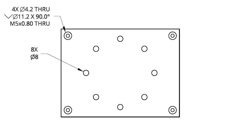
Tip #3: Consolidate Call-Outs When Multiples of the Same Feature Exist in a View
For features that repeat throughout your part, dimension only one instance of the feature and label the dimension as “#X DIM”, meaning that the feature exists in that view X number of times. For example, “4X 10-32 TAP” implies that in the view, there are four 10-32 threaded holes.
This is a widely utilized callout, so manufacturers will recognize it quickly. Just be careful when utilizing the same method for similarly sized features like radii or holes, as one could become easily confused with another. So, say you have 8 holes visible in one drawing view and 4 of them are 0.50” in diameter, while the other 4 are 0.55” in diameter. It may be difficult for the manufacturer to discern this difference between the two sizes.

Tip #4: Communicate Assembly Intent of Critical Features
You should provide an assembly drawing or instruction if an entire assembly is being machined. Alternatively, provide the part number so the machinist can look up off-the-shelf hardware.
For example, suppose you have a hole in your design that is made to fit a dowel pin from McMaster-Carr (P/N 97395A452). For this particular dowel pin, you would specify a hole size with a nominal diameter of 0.1252”. By providing a flag note for the dowel pin, the manufacturer knows what item you plan to install in that location (the dowel pin P/N). This may seem like an over-explaination, but providing this extra information can help your manufacturer during machining.
Furthermore, you should remember the assembly intent when defining the datum reference planes for your parts — the critical mating surfaces are a good place to start when defining these planes.
Tip #5: When Hardware Installation is Required, Provide the Supplier and Part Number
Simply noting “press-fit M4 dowel” doesn’t give a machine shop dowel length or material information. Instead, add a flag note with a supplier name and P/N, or, if it’s a standard part, specify the part by the full standard.
Tip #6: Limit References to Secondary Documents Within Drawings When Possible
Having been personally responsible for reviewing drawings requirements from both a quality and engineering perspective, it’s a test of patience and determination to sort through links, supplier portals, and even specifications to find relevant requirements. And, some are in the wrong location or aren’t relevant to the part being manufactured.
So, here’s how to simplify references to secondary documents for requirements:
- Put all document references in the same location. It doesn’t matter if it’s the purchase order, RFQ, or drawing notes. What does matter is maintaining that location as a single reference point.
- Note the requirements that exist on the drawing, at a minimum. So, if your secondary document requirements are listed on the purchase order, specify this in a drawing note. The drawing is what your manufacturer and their engineering team will likely review first and the most closely.
- If the requirement is static or won’t change with the order when the drawing is released to the customer, put the requirement on the drawing instead.
Tip #7: Don’t Over-Dimension or Over-Tolerance Your Designs
Typically, only a few features on a part are critical to its function, so you want the machinist to pay extra attention to these features. When you over-dimension, the critical requirements are lost in the noise, so assign only tolerances to mission-critical features. Also, over-dimensioning will drive up the cost of the prototype.
Tip #8: Make Sure Drawing Annotations Account for Quality Control
Whether your designs require simple hand metrology or sophisticated CMM techniques to validate that dimensions and features are within the specified tolerances, you should always consider quality (especially how these dimensions will be measured) when designing a part. You should build quality in your designs. The field of metrology is complex but you don’t need to be an expert in it to ensure your designs are made with quality in mind. For a refresher, check out our article What is Metrology? An Overview & Explanation.
Pro-Tip: Consider Fictiv for all your CNC, 3D printing, urethane casting, and injection molding manufacturing needs. Our platform gives you real-time production and quality control tracking so production timelines are fully transparent. Watch the video below to learn more:
Tip #9: Consider the Value of
Advanced Inspection vs. Simple Inspection
When finalizing your design, consider that some GD&T controls can’t be easily verified with hand metrology tools, which is the standard in quick-turn prototyping. Consider which design stage you’re in and try to match it with the level of inspection you require per drawing controls and GD&T markups on your drawings. For example, surface roughness will often require an advanced inspection method (profilometer readings), while a general note about no machining marks or chatter will require a simple visual inspection.
The good news is that if you require advanced inspection (including GD&T), Ficitv offers the ability to request this at configuration prior to purchase.
Key Takeaways
Technical drawings are still an essential part of communicating design intent for CNC machined parts, even with the increased popularity of model-based definitions. However, not all engineers receive adequate training on creating manufacturing drawings.
This leadis to non-standard formatting, over-tolerancing, and other issues that adversely affect lead times, part costs, and specification clarity. By employing the tips in this article, you can create better technical drawings that effectively communicate your critical requirements, save time and money, and ensure you get accurate, quality parts.
So, the next time you get the urge to apply a control to a drawing feature, ask yourself: is this critical for assembly, and is this requirement measurable? Call out that dimension only if you answer “yes” to both.
For all your manufacturing needs, even with requirements specified on a 2D drawing, choose Fictiv. You can even generate a 2D drawing on the platform!

At Fictiv, we make custom manufactured parts at ridiculous speeds. Submit a part for an instant quote or create a free online account today!


