Time to read: 15 min
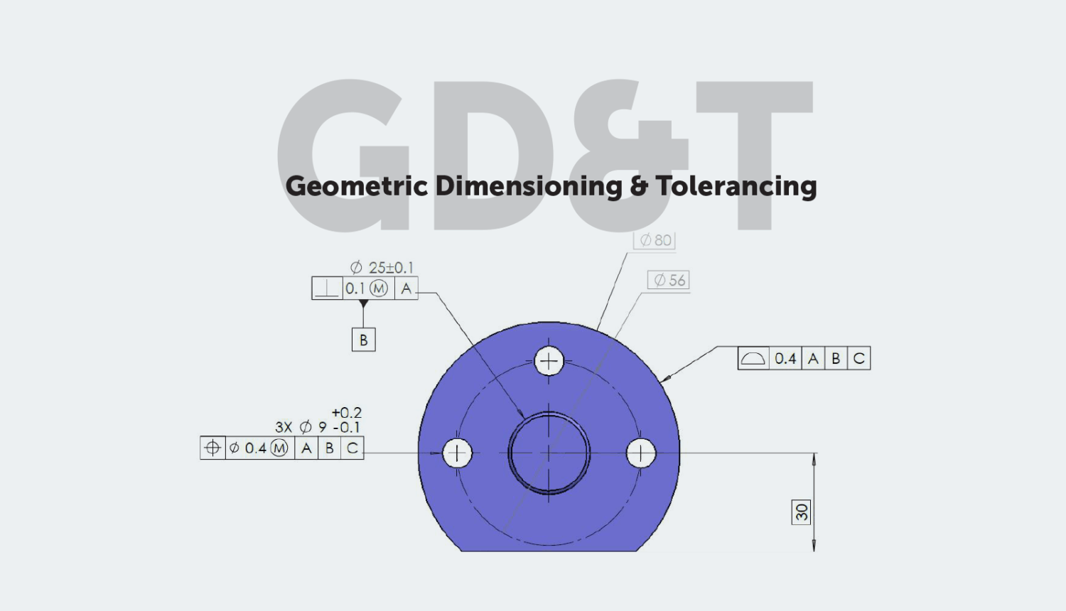
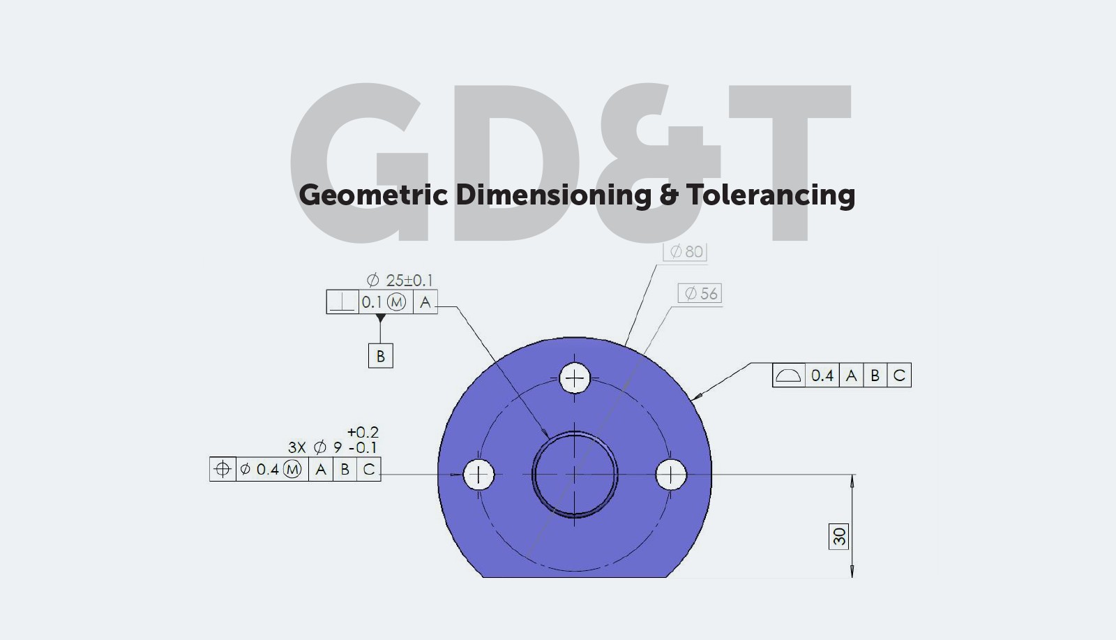
Geometric Dimensioning and Tolerancing (GD&T or GD and T) is a standardized system that uses symbolic language to define and communicate product geometry, design intent, and engineering dimensions and tolerances, ensuring precise control over manufacturing variations.
Download the free eBook version and master the fundamentals of GD&T— including tips, terms, and best practices, all in one place.
In this guide on Geometric Dimensioning and Tolerancing (GD&T), we’ll cover:
Table of contents
- Overview of GD&T
- GD&T Symbols
- GD&T Symbol Categories
- Top 20 Most Common GD&T Symbols
- GD&T Material Condition Modifiers
- GD&T Feature Control Frames
- GD&T Feature Control Frame: First Compartment
- GD&T Feature Control Frame: Second Compartment
- GD&T Feature Control Frame: Final Compartments
- Surface Finish
- GD&T Tips for Large Parts
- Conclusion
- 💡 GD&T Best Practices and Common Mistakes
- Ready to Start Your Next Project?
Overview of GD&T
History of GD&T
The original concept of GD&T is credited to Stanley Parker, an engineer at the Royal Torpedo Factory in Scotland during World War II. Parker observed that parts for naval weapons were continuously being rejected due to imperfect measurements, even if the discrepancy was tiny and the part would still be functional. In response, he published two works introducing the foundations of GD&T and the concept of True Position (aka Position).
True Position: The ideal or theoretical exact location of a feature on a part, serving as a reference point for measuring deviations (tolerances) during manufacturing or inspection.
In the 1940s, the U.S. military developed the first standards for GD&T with the publication of the (later revised) MIL-STD-8. GD&T has evolved since then and is now commonly used across the industry.
ASME Y14.5 (last revised 2018, at the time of posting) is now considered the standard for GD&T.
What Is GD&T?
GD&T is a system for defining and describing engineering dimensions and tolerances that differs from traditional methods like coordinate square tolerancing and plus/minus tolerancing.
Coordinate Tolerancing: A method where the acceptable tolerance zone for a feature is defined as a square (equal tolerance in two perpendicular directions, X and Y).
Plus/Minus Tolerancing: A method that specifies allowable variation as a range (e.g., ±0.05 mm) around a nominal dimension.
Nominal Dimension: The intended or target size of a feature, from which allowable variations (tolerances) are specified.
During the design phase, often performed with Computer Aided Design (CAD), engineers propose parts with perfect geometry—but manufactured parts are not entirely perfect. These imperfections may cause issues with on-time delivery and the total cost of parts in the form of rework and scrap.
Proper use of GD&T can improve product quality and reduce the time and cost of parts by
- Providing a common language to express design intent accurately
- Focusing on functional interfaces (the critical areas or surfaces of a part that interact with other parts and directly affect performance) to tolerance a part
💡 Best Practice: Deepen your understanding of GD&T to help improve product quality through communications with your cross-functional manufacturing teams.
Benefits of GD&T:
- Provides a standardized design language
- Enables clear, precise, and consistent communication between all parties involved in designing, producing, and inspecting a part
- Offers a method for calculating worst-case mating limits (total permissible variation between mating parts that fit together)
- Supports repeatable and reliable production and inspection processes
- Ensures proper assembly using qualified production parts
Pro-Tip: Fictiv’s AI-powered platform and global network of vetted manufacturing partners ensure your design intent, specified through GD&T along with drawing notes, is always met and the highest quality standards are repeatably followed.
Tolerances
A tolerance is the permissible amount of variation for a physical feature in a manufactured part—i.e., how different a feature’s real-world location or measurement is allowed to be from the ideal location or measurement from the design
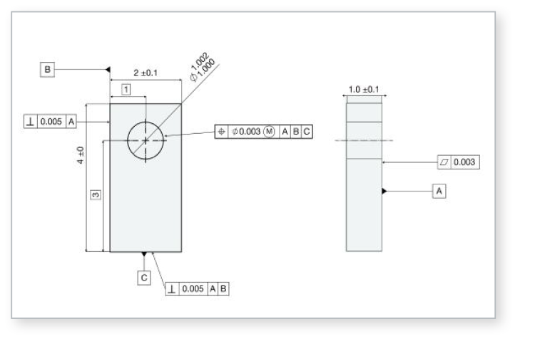
It’s important to keep tolerances on engineering drawings in perspective—tolerances for a given part may not be visible to the naked eye, but they can have a big impact on the performance of the part or assembly.
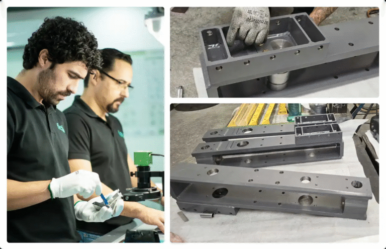
At first, manufactured parts may appear flat, straight, or perfectly shaped—but if you were to precisely measure them at every cross-section, you’d uncover subtle imperfections. These variations are normal and expected. Tolerances define the allowable limits for such variations, acknowledging that no part can ever be truly perfect. They’re carefully selected to ensure functionality while accommodating the inherent variability of real-world manufacturing processes.
As a general rule, engineers and designers should strive to keep tolerances as large as possible. Small or tight tolerances can increase costs for manufacturing, inspection, and tooling. Tight tolerances are sometimes necessary, but it’s best to make them as loose as you can to save on those costs.
To provide some context, let’s consider the diameter of an average human hair: around .005 inches. In general, tolerances of +/- .005” are expected and achieved from today’s CNC mills. However, just because you can hold tolerances smaller than a human hair doesn’t mean you need to (or that you should).
💡 Best Practice: Keep tolerances as large as possible to save on manufacturing costs. Learn how to conduct a tolerance analysis.
GD&T vs. Traditional Coordinate Tolerancing
GD&T differs from coordinate tolerancing (also known as conventional tolerancing or square tolerancing). Coordinate tolerancing focuses on square or rectangular tolerance zones formed around X, Y, and Z coordinates.
GD&T includes circular or cylindrical tolerance zones formed around a point—resulting in a 57% larger tolerance zone.
GD&T vs. Coordinate Tolerancing: Key Differences
| Aspect | Coordinate Tolerancing | GD&T (Geometric Dimensioning and Tolerancing) |
| Tolerance Zone Shape | Square or rectangular zone defined by ± tolerances in X and Y directions. | Includes circular, cylindrical, or profile-based zones tailored to the feature’s function. |
| Interpretation | Allows independent variation in X and Y; can lead to looser positional control diagonally. | Controls total positional variation using geometric features like true position. |
| Form and Orientation Control | No direct control over form (e.g., straightness, flatness) or orientation (e.g., perpendicularity). | Explicit controls for form, orientation, and runout. |
| Feature Control | Only controls size and position using basic dimensions. | Controls size, form, orientation, and location as independent or related characteristics. |
| Functional Fit Assurance | May result in interference or misalignment due to poor orientation or combined variation. | Ensures functional fit by referencing datums and controlling functional interfaces. |
| Design Intent Communication | Implicit; often leaves interpretation to manufacturer or inspector. | Explicit; symbols convey intent unambiguously and consistently. |
| Manufacturing Flexibility | Can be overly restrictive or lenient, depending on how tolerances are applied. | Allows looser tolerances on non-critical areas while tightly controlling critical ones. |
| Inspection Alignment | Assumes inspection from a single fixed coordinate system. | Aligned to real-world functional datums used in actual assemblies. |
| Use Case | Simpler parts, traditional drafting environments, and straightforward inspection. | Complex profiles, assemblies with tight functional requirements, and modern manufacturing systems. |
GD&T Tolerancing vs. Coordinate Tolerancing: Practical Example
| Coordinate Tolerancing | GD&T Tolerancing |
| Drawing Callout: ⌀10.00 ±0.05 mm Center located at X = 50.00 ±0.10 mm, Y = 30.00 ±0.10 mm | Drawing Callout: ⌀10.00 ±0.05 mm Position: ⌖| ⌀ 0.10 Ⓜ | A | B | C |
| Interpretation: The size of the hole must fall between 9.95 mm and 10.05 mm. The position is controlled independently in X and Y directions within ±0.10 mm. The tolerance zone is a square (or rectangle) around the nominal center. Does not control orientation or perpendicularity of the hole. Can result in a larger diagonal positional error, up to √(0.10² + 0.10²) ≈ 0.14 mm. | Interpretation: Same size tolerance: 9.95 mm to 10.05 mm. The hole’s axis must lie within a cylindrical positional tolerance zone of diameter 0.10 mm, oriented and located relative to datum features A, B, and C. Controls position, orientation, and coaxiality in 3D space. Provides uniform error distribution in all directions, reducing risk of misalignment. |
Datums and Datum Features
A datum is an ideally or theoretically exact point, axis, or plane used as a reference for measuring and manufacturing part features.
In design engineering, the Datum Reference Frame (DRF) is a three-dimensional Cartesian coordinate system used to define the part’s tolerances, tolerance symbols, and geometric features. It’s arguably the most important concept in GD&T and has a significant impact on the part manufacturability and inspectability.
The DRF acts as the “skeleton” of the geometric system: it’s the foundational framework upon which all geometric specifications are built. It serves as the reference from which all dimensions and tolerances are defined. Ideally, the DRF should reflect how the part is assembled in the real world.
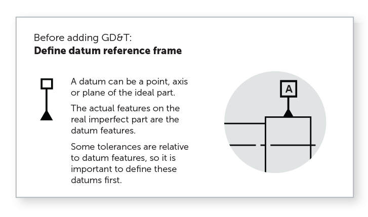
A DRF establishes a part’s Six Degrees of Freedom (6DoF or DOF): the freedom of movement a rigid object has in 3D space, including three linear translations (forward/backward, up/down, left/right) and three rotations (about the X, Y, and Z axes). To accurately design, manufacture, and verify parts, these degrees of freedom must be constrained.
By mating parts to the Datum Reference Frame, consistent DOF measurements, processing, and calculations can be performed.
There’s an important distinction between datums and datum features:
Datum vs. Datum Feature
| Term | Definition | Key Point |
| Datum | An ideal point, axis, or plane used to establish the Datum Reference Frame (DRF). | Ideal and flawless; used as the reference for geometric control. |
| Datum Feature | The actual, physical feature on the part (e.g., hole, face, slot) selected to establish a datum. | Real-world features with inherent variation and imperfections. |
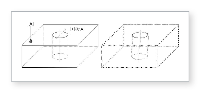
When defining a part, an engineer will identify the datum features that are most important to the functional requirements of the design—usually, the features that interface with other components in an assembly. Datum features referenced in a Feature Control Frame (a frame defining the conditions and tolerances of a specified feature) will, in order of precedence, orient the part to the Datum Reference Frame.
A Feature of Size (FOS) is any geometric feature defined by size dimensions such as length, height, diameter, angle, etc. A feature of size may serve as a datum (think a hole, post, or slot).
To determine whether a feature qualifies as a feature of size, you can apply the Caliper Rule: If you can place the tips of a caliper around (for external features) or inside (for internal features) the part and both tips make contact with opposing surfaces, then the feature is considered a feature of size.
If you must use the probe end of the caliper to take the measurement—meaning you can’t span opposing surfaces—then it is not a feature of size.
Tolerances can be applied to features of size. When orientation tolerances (like perpendicularity or angularity) are applied to a feature of size, they control the orientation of the feature’s axis or midplane within a defined tolerance zone, relative to a datum at a specified basic angle.
GD&T Basic Dimensions
Basic dimensions are theoretically exact numerical values used to define the form, size, orientation, or location of a part or feature. Basic dimensions are usually shown on a drawing enclosed in a box, but they can also be invoked by referencing a standard or by a note on the drawing. The CAD model itself can also be defined as basic.
Permissible variations from basic dimensions are usually defined in the GD&T feature control frame or via notes on the drawing. Default tolerances listed in the title block of a drawing do not apply to basic dimensions.
Often, basic dimensions are not utilized for quality inspection purposes. Although they are measured during inspection, they don’t typically have associated tolerances and therefore are not used for pass/fail criteria. Instead, they serve to locate or orient features relative to datums, with allowable variation controlled by associated GD&T tolerances.
GD&T Symbols
GD&T is a feature-based system in which all parts are composed of features. Geometric tolerances are applied to features with feature control frames, utilizing a series of symbols to describe the tolerance allowed. These geometric characteristic symbols are usually what come to mind when people think about GD&T.
GD&T symbols fall into four main categories (or characteristics of features): form, orientation, location, and runout.
GD&T Symbol Categories
| GD&T Category | Description | Key Notes | Characteristic of Feature Examples |
| Form | Controls the shape of individual features. | Often used as a refinement of size, i.e., further restricting or controlling a feature beyond its size tolerance. Does not require a datum reference. | Straightness, Flatness, Circularity, Cylindricity |
| Orientation | Controls the tilt or angularity of features. | Always based on basic angle dimensions. Often used as a refinement to location, i.e., further controlling a feature’s direction or angle relative to a datum (after basic location has been established). Requires a datum reference. If applied to surfaces, also controls form. | Parallelism, Perpendicularity, Angularity |
| Location | Controls the exact placement of features using basic linear dimensions. | Locates features or features of size based on the feature itself or a set of median (center) points. Versatile and powerful; may control size, form, and orientation together. | Position, Concentricity, Symmetry |
| Runout | Controls the variation of a surface as it rotates about an axis. | Requires a datum axis. Used to evaluate rotating features or surfaces. | Circular Runout, Total Runout |
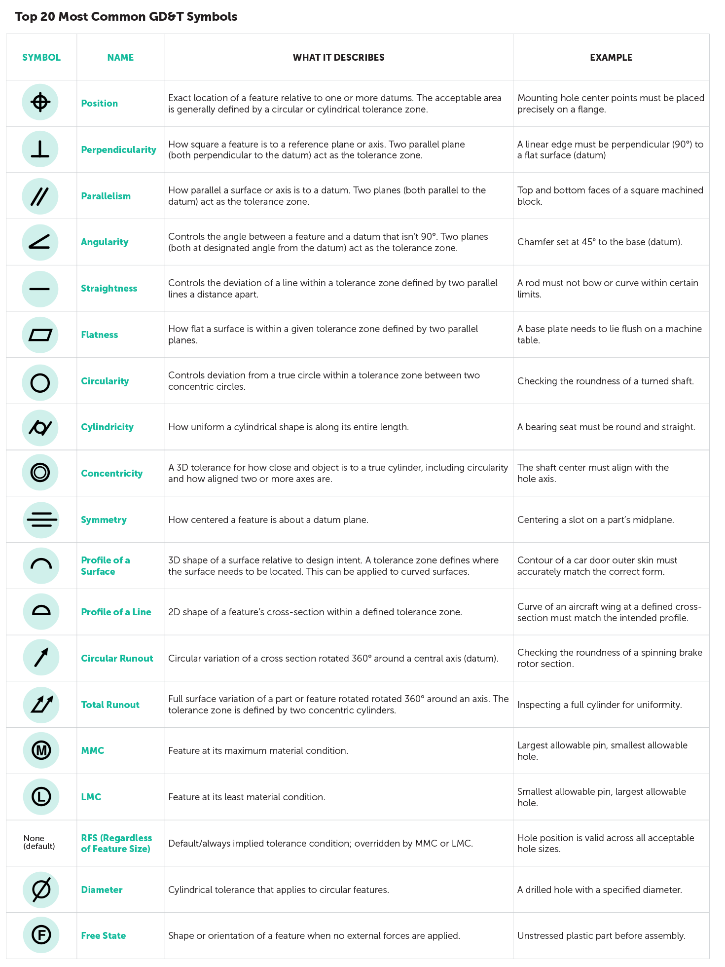
Here’s a quick cheat sheet for some of the most common GD&T symbols, their meanings, and a practical example of each:
Top 20 Most Common GD&T Symbols
GD&T Material Condition Modifiers
When specifying geometric controls, it’s often important to indicate that a tolerance applies to a feature at a particular size. Maximum Material Condition (MMC) and Least Material Condition (LMC) are modifiers used to communicate that intent clearly.
Maximum Material Condition (MMC) vs. Least Material Condition (LMC)
| Term | Definition | Example |
| Maximum Material Condition (MMC) | The state in which a feature contains the most material within its size limits. | Largest allowable pin or smallest allowable hole. |
| Least Material Condition (LMC) | The state in which a feature contains the least material within its size limits. | Smallest allowable pin or largest allowable hole. |
These material condition modifiers are placed in the feature control frame after the geometric tolerance value. As the feature deviates from its stated condition (MMC or LMC), additional geometric tolerance—often called “bonus” tolerance—is allowed, increasing manufacturing flexibility without compromising function.
| Term | Definition | Context/Use |
| Bonus Tolerance | Additional tolerance that becomes available when a feature of size departs from its Maximum Material Condition (MMC) or Least Material Condition (LMC). | Commonly used in position control for holes or pins, allowing greater tolerance as the feature becomes easier to produce (e.g., a hole gets larger). |
In the illustration below, the MMC (Ⓜ) of the hole is 19.5 mm, and the LMC (Ⓛ) is 20.5 mm.
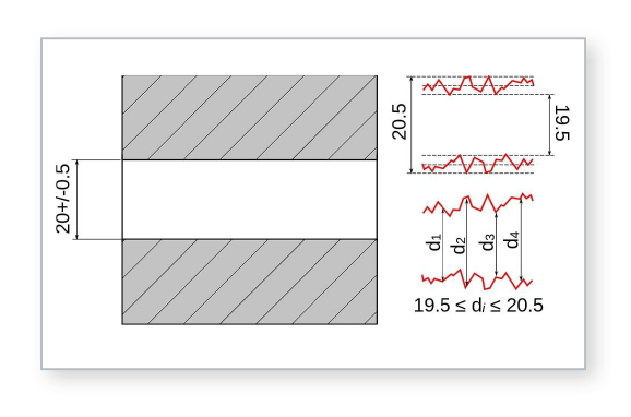
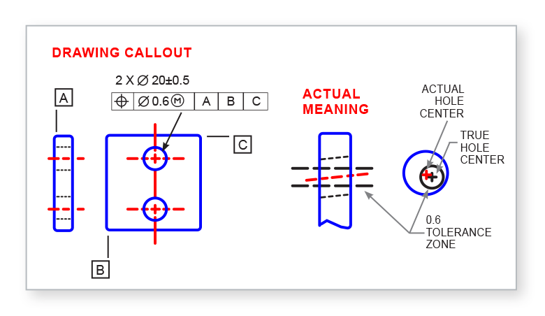
Consider a hole specified at diameter (⌀) 20 ±0.5 mm with a position tolerance of 0.6 mm at MMC. This means the tightest positional tolerance (0.6 mm) applies when the hole is at its MMC size of 19.5 mm. As the hole increases in size (moving away from MMC), it gains bonus tolerance equal to the amount it departs from 19.5 mm.
If a hole measures 20.0 mm, it is 0.5 mm larger than the MMC, so the allowable position tolerance increases to 1.1 mm (0.6 mm + 0.5 mm). This is how bonus tolerance allows greater flexibility without compromising function.
GD&T Feature Control Frames
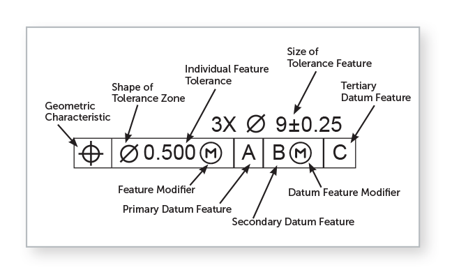
A feature control frame is a callout box that states the requirements or instructions for a specified feature.
(In other words, the feature control frame is a frame that controls features. It’s nice when things are easy.)
Each feature control frame contains only one message, so if a feature requires two messages, it requires two feature control frames.
GD&T Feature Control Frame: First Compartment
The first compartment of a feature control frame contains a geometric characteristic symbol, which defines the type of control being applied to the feature. Only one symbol can be placed in a feature control frame. If a feature has multiple requirements, they must be specified using separate feature control frames or a composite tolerance.
GD&T Feature Control Frame: Second Compartment
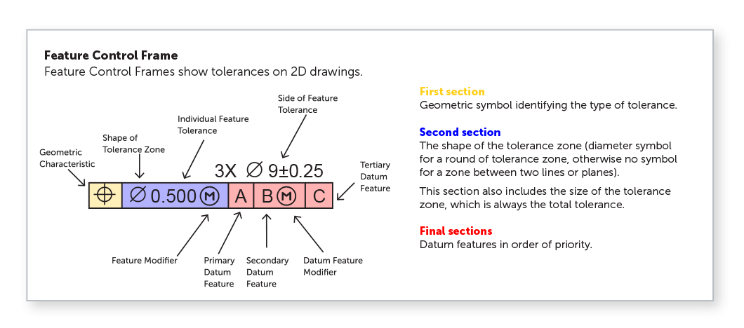
The second compartment of a feature control frame contains the feature’s total geometric tolerance. This tolerance is expressed as a single value—never as a plus/minus range.
If the feature tolerance is preceded by the diameter symbol (⌀), the tolerance zone is understood to be cylindrical. This is commonly used for controlling the position of holes. If there is no symbol preceding the tolerance value, the default tolerance zone is defined by two parallel planes. This type of zone is typically used for features like slots or the profile of a surface.
After the feature tolerance in a feature control frame, a material condition modifier—such as Maximum Material Condition (MMC) or Least Material Condition (LMC)—may be specified for a feature of size, like a hole. If no modifier is shown, the default is RFS (Regardless of Feature Size), but this is not included in the feature control frame. For features that are not features of size, such as a plane surface, material condition modifiers cannot be used.
GD&T Feature Control Frame: Final Compartments
The final compartments in the feature control frame contain the datum feature references, if needed. For example, form controls like flatness or straightness do not use datums, while location controls such as position typically require datum references.
While the letters used to identify datums (e.g., A, B, C) may suggest order, what matters is the sequence in the frame, which defines their order of precedence: primary, secondary, and tertiary, read left to right. Often, however, Datum A will be the primary datum, followed by B and C.

The primary datum is the first reference used to establish a part’s position and orientation. It’s the first feature contacted (meaning, the first surface of the part that physically touches and is constrained by a datum simulator), requiring a minimum of three points of contact. The secondary datum is the second feature contacted, with at least two points of contact, and the tertiary is the third feature contacted, with a minimum of one point.
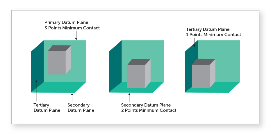
When all three datum features are contacted simultaneously, they establish three mutually perpendicular planes, forming the Datum Reference Frame (DRF). The DRF is not abstract—it is realized through datum simulators, physical tools and equipment used in manufacturing, inspection, and processing. These include devices like surface plates, collets, three-jaw chucks, and gage pins, which physically simulate the datum features of the part.
Surface Finish
Surface finish refers to the texture and smoothness of a part’s surface and plays a critical role in performance, fit, and function—especially in applications involving sealing, friction, or aesthetics.
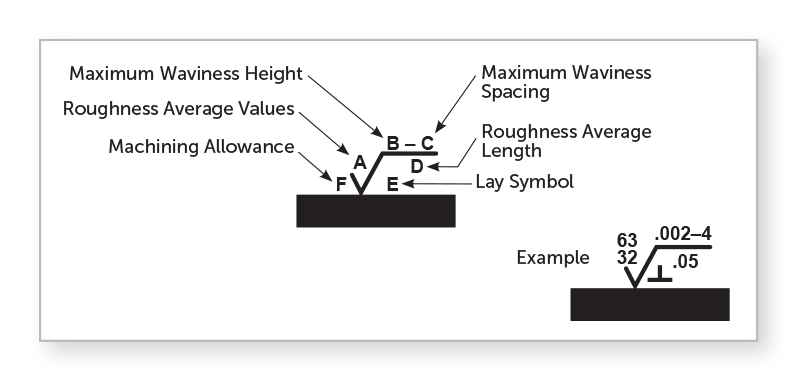
In technical drawings, surface finish is typically specified using symbols defined by the ASME Y14.36M standard. A complete surface finish specification may include:
- Roughness (Ra): Measured in micrometers (µm) or microinches (µin), this indicates the average surface deviations.
- Lay: The predominant direction of the surface pattern (e.g., parallel, circular).
- Waviness: Larger periodic irregularities caused by machine or material movement.
Additionally, ASME offers the B41.6 Surface Texture Standard, which outlines key definitions and measurement techniques for achieving the right surface finish. ISO 1302 and ISO 4287/4288 may also apply for international applications. Remember, surface finish isn’t just one thing; it is made up of three crucial elements: roughness, lay, and waviness.
A smoother surface can improve sealing, and reduce wear or friction. A rougher finish may help with coating processes and adhesion. Keep in mind that tight surface finish requirements can increase manufacturing cost and inspection complexity, so these specifications should be applied only to critical surfaces.
GD&T Tips for Large Parts
Reference Datum Features Carefully
Use robust, easily accessible datums—like large flat surfaces or machined holes—not surfaces that may warp or shift.
Remember that the raw material properties, internal stresses, and geometry impact the flatness. Drawn materials like 5000 series aluminum are more susceptible to warping, while cast raw materials like MIC6 aluminum are not as susceptible. Material selection is especially critical when tight tolerances are needed for large CNC parts.
To mitigate warping and enable tighter flatness tolerances for large parts, you may consider adding flanges on the sides of a long or large part, which can reduce internal stresses. For large parts, select datums that are less likely to be distorted during inspection, especially for flexible or thin-walled components.
Account for Fixturing and Inspection Limits
Clearly define datums and tolerances that realistically account for how the part will be fixtured both during machining and in inspection. Large parts may need multiple setups, so break up tolerances by zones if needed.
Use Datum Targets for Large or Irregular Surfaces
Datum targets should be considered for GD&T of large parts. Datum targets can be tools, like spherical pins, round flat-bottom pins, or three-jaw chucks, that help define reference points in manufacturing. They create datum planes or axes, which are essential for accurate measurements. These targets make contact with specific features of a part and are typically used to inspect items that are not perfectly round, straight, or flat, or for larger components that require precise alignment. This ensures clarity in how the part should be inspected.
Use Profile Tolerances Thoughtfully
Profile of a surface or line works well for controlling large, complex surfaces. It allows for controlled deviation across the entire surface, ideal for parts that may warp slightly during machining.
Conclusion
Now that you’ve reviewed our tips for GD&T, you’re ready to submit your well-defined drawings in tip-top shape.
💡 GD&T Best Practices and Common Mistakes
✅ GD&T Best Practices
| Best Practice | Description | Why It Matters |
| Define Datums Based on Functional Assembly | Choose datum features that reflect how the part is actually mounted, assembled, or used. | Ensures measurements and tolerances are meaningful and repeatable across manufacturing and inspection. |
| Use GD&T Only Where It Adds Value | Apply geometric controls only to critical features affecting fit, form, function, or performance. | Keeps drawings clean, reduces inspection burden, and focuses tolerancing where it matters most. |
| Communicate Design Intent Clearly | Use appropriate symbols, modifiers, and feature control frames to describe how the part should behave. | GD&T is a language—use it to express function and performance, not just geometry. |
⚠️ GD&T Common Mistakes
| Common Mistake | Description | Why It’s a Problem |
| Overdimensioning | Applying GD&T to every feature, even non-critical ones. | Leads to increased cost, complexity, and unnecessary inspection effort. Not all features need geometric controls. |
| Improper or Missing Datum Structure | Using non-functional or unstable features as datums. | Results in inconsistent measurements or part misalignment. Weak datums compromise the entire tolerance scheme. |
| Confusing Size and Form Controls | Assuming size tolerances automatically control form (they don’t unless explicitly paired). | Can lead to unexpected deviations. Form controls like flatness or straightness must be applied separately. |
❗️ Not done learning about GD&T? Check out these Fictiv resources:
- CNC machining tolerances
- The Datum Reference Frame
- Applying Geometric Symbols to Engineering Drawings
- Material Condition Modifiers
- The Feature Control Frame
Ready to Start Your Next Project?
Fictiv simplifies custom manufacturing at every stage from prototype to full-scale production.
Get instant quotes, DfM feedback, and transparent order tracking—plus, access to a Fortune 500-class global supply chain and a team dedicated to quality and on-time delivery.
Get started with an instant quote today.


