Time to read: 7 min
CNC (Computer Numerical Control) machining is an automated, subtractive manufacturing process where a CNC machine is controlled with a set of commands that, when followed, will produce a part. CNC operators create these commands through a process called CNC programming. This article describes CNC programming and the different types of CNC programming methods.

What Is CNC Programming?
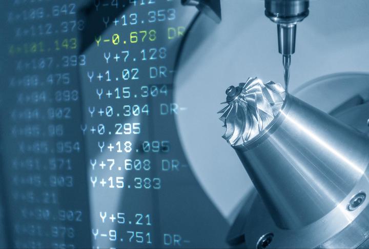
Modern CNC programs are complex and are often generated using CAM (Computer-Aided Manufacturing) packages. Machinists import the CAD (Computer-Aided Design) model into the CAM package and then configure the tooling, speeds and feeds, machining operations, and toolpaths. Once the CAM software creates the program, the code for the CNC machine — referred to as G-code — can be generated and post-processed to function on specific CNC firmware.
G-code is a machine-readable list of instructions that tells the machine where and at what speed to move the tool. G-code used to be generated by machinists one step at a time by listing individual instructions for the machine to follow. It’s still possible to modify G-code for more advanced functionality, but the vast majority of G-code is automatically generated by CAM packages. More precisely, G-code refers to machine instructions that control the movement of the machine, whereas M-codes specify various machine functions.
CNC programmers can modify the code to create custom behaviors and enhanced functionality using one of three methods — by using macros, subroutines, or parametric programming.
Macros in CNC Programming
If you have used Excel, you are probably familiar with macros — a macro in Excel is a set of input sequences that performs what some keystrokes or mouse operations would have performed. Basically macros are pre-programmed operations that are simple to use and save time. In CNC machining, a macro is a set of programmatic instructions most often used for automating repetitive tasks and saving on programming time. Macros in CNC programming can be used to store variables, perform mathematical operations, and execute logic statements.
Here are some common macro structures in CNC programming:
Variables
A variable can be set in G-code using the “#” key. For example, a variable can be assigned to a value or a G-code command, such as:
- Variables: For example, #201 = 5 means that variable name 201 stores the value 5.
- Commands: Now, G5 X#201 is the same as G5 X5, so when the G5 command is executed, the machine must move 5 units in the x-axis.
There are many different types of variables, but these are three of the most common:
- System Variables are assigned by the CNC control manufacturer and cannot be used in a CNC program. They typically control the setting of default parameters.
- Local Variables are used within the body of a macro and are only kept in memory as long as the file is being run.
- Common Variables are similar to global variables and are stored in memory after running the macro. They’re useful for keeping track of tool-wear values that are updated whenever a new macro is run.
Mathematical Operators
Normal mathematical operations like add “+”, subtract “-”, multiply “*”, or divide “/”, and raise to the power of (^), can be used to modify values. Logical operators can also be used to evaluate expressions, for example, “AND”, “OR”, and “XOR”.
Mathematical Functions
Functions are useful for calculating specific numerical results dependent upon a user-provided variable. For example, to get the absolute value of a negative number, the “ABS” function can be called. Another example is the square root function “SQRT” which calculates the square root of a number.
Comparators
Comparators evaluate a set of values as either true or false. For example, to check if two values are equal, the “EQ” comparator can be used. Other useful comparators include not equal to “NE”, or greater than “GT”. When a comparator evaluates to “true”, it will output the value “1” and when it evaluates to “false” it will output the value “0”.
Statements
Statements are used to control the flow of a program, and some statements must be used together. For example, the “IF” – “THEN” statement can be used to check a value using a comparator, then execute an operation if the comparator evaluates to “true”. Other statements include “WHILE” – “DO”, which continuously performs a set of operations as long as a comparator evaluates to “true”. Using these statements is also referred to as ‘branching and looping.’
Macro Applications
There are many applications for basic macros, and here are some common examples:
- Tool Counting: A macro can be used to keep track of a tool’s life by tracking the number of hours it has been actively cutting material. This can help identify worn-out tooling before it fails, which can potentially scrap a part.
- Part Counting: A macro can be used to keep track of how many times a certain part has been produced.
Subprograms in CNC Programming

A subprogram is macro code that can be called and executed in the main G-code file, and can be called multiple times within a single main file. This allows a programmer to save time by reusing code that has already been created. Subprograms are better than just copying existing code into the main G-code file. Without them, when a change is required inside the relevant code, then all the G-code files that use the code must be updated manually. However, with subprograms, this update only needs to be done inside the subprogram, and all G-codes that use the subprogram will reference the new code.
Calling a Subprogram
To call a subprogram inside a main program, a specific G-code command must be used:
- M97: When using the M97 command, the subprogram must be inside the main file. Specifically, it needs to be at the end of the main file after the M30 command. The M30 command signifies the end of a main program file. This should not be used if the subprogram is used in multiple main files and may need to be changed in the future.
- M98: When using the M98 command, the subprogram must be stored in a separate file and does not form part of the main file. This is ideal for applications for which the subprogram is used in many G-code files.
Now, let’s look at an example, calling a subprogram from the main file using the following command:
M98 P1234 L1
The first M-code tells the main program where to find the subprogram, either at the end of the main program (M97) or in a separate file (M98). The next P-code identifies the specific subprogram to be called. Finally, the L-code indicates how often the subprogram must be run.
Subprogram Structure
A subprogram has the same general structure as a normal main file with a few differences, as indicated in the example below:
O1234; refers to the program number. Body of subprogram code that makes use of standard G-code commands and macros
M 99; identifies the end of the program. Unlike main files terminated with M30, subprograms are terminated with M99, which returns the program to the main file.
Subprograms can be nested inside each other, which means that a subprogram can call another subprogram — note that the exact syntax depends on the CNC machine being programmed for.
Subprogram Applications
There are many different applications for subprograms, for example:
- Logo Engraving: If the same logo must be engraved on multiple parts, a simple subprogram can be called inside the existing G-code.
- Slotting: A standard slot size can be defined by a subprogram and can be called wherever required inside a main file.
Parametric CNC Programming
Parametric CNC programming is a method used to create a family of parts or features whose dimensions can be defined by mathematical functions. The programmer can enter the parameters of these functions, and the program will be evaluated based on these parameters.
For example, a program for a cylinder can be created in which the parameters are the outer diameter and the height of the cylinder. The parametric program will take these values and feed them into a subprogram that updates all the relevant commands to reproduce the cylinder. This means the code does not need to be manually changed with the new sizes and can be reused for many different part sizes. Put simply, a parametric CNC program is a subprogram in which all the relevant values are not hard-coded, but rather refer to a set of variables that the programmers add.
Calling a Parametric Subprogram
A parametric subprogram can be called using the G65 code specific to parametric files. This contrasts the M97 and M98 codes used to call standard subprograms. For example, a parametric subprogram can be called using the following code:
M65 P4567 A1.0 B2.0 C3.0
The first M-code tells the main program that it must call a parametric subprogram and must expect variables. The next P-code identifies the specific parametric subprogram to be called. The next set of codes, namely A, B, and C, refer to the parameters that will be used inside the parametric subprogram.
Parametric Subprogram Structure
A parametric subprogram has the same general structure as a normal subprogram, with a few differences you can see in the example below:
O4567; This refers to the program number
; Declaring of local variables
#1
#2
; Body of Subprogram Code. Makes use of standard G-code commands and macros
G00 X #1 Z #2; Rapid traverse using the values stored in variables #1 and #2
M 99; End of the program. Unlike main files terminated with M30, parametric subprograms are terminated with M99, which returns the program to the main file.
Note: This is just an example, and the exact syntax depends upon the CNC machine you’re using.
Applications of Parametric CNC Programming
Below are two examples of how a simple parametric program can be used:
- Simple Part Family: A parametric program can be used to define a family of parts with the same general geometry, but with different overall dimensions. For example, a bolt can be defined by its head size, length, shank diameter, and thread type. A parameterized subprogram can be called by defining these values without creating a new file for each bolt.
- Features: Common features like slots can be parameterized. For example, a slot can be defined by its length, width, and depth, and parameterized subprogram can be called that will reproduce the slot according to the entered values.
CNC Machining With Fictiv
Fictiv is your operating system for custom manufacturing, whether you’re CNC machining, injection molding, laser cutting, 3D printing, or urethane casting. Our global network of manufacturing partners is highly vetted and our machinists are incredibly skilled — it’s how we can produce complex parts so quickly!
To get started with Fictiv’s CNC machining service, create your free Fictiv account and request a CNC machining quote today!


