Time to read: 6 min
Gears can be fabricated using a myriad of different manufacturing methods. As you may expect, the profile of the teeth needs to follow specific dimensions and constraints in order to transmit torque, prevent slippage and excessive undesired contact stresses. Therefore, the fabrication process you select should accomplish the necessary tolerances and properties. This article will go over the process of Electron Discharge Machining in gear manufacturing.

Before we start, here are some terms you need to know:
- Gear blank: The material/block of the gear before the teeth profile is defined. It could be a cylindrical block, or another geometry like a rack, cone, etc.
- Workpiece: The material that will be cut to produce a specific geometry. A gear blank can be a workpiece, but not all workpieces are gear blanks, since the described manufacturing process can be used for other types of designs.
- Cutter: The tool used to cut the workpiece. In EDM, the cutter is sometimes called the electrode.
What is EDM?
Electron discharge machining (EDM) is a manufacturing process where material is removed from the workpiece by applying a series of current discharges between two electrodes separated by a dielectric bath liquid.
EDM Types:
- Wire Cutting Electrical Discharge Machining: In this type of EDM process, a wire is used as an electrode, and it is continuously fed from the automatic feed with a spool during the process. Typically the fluid is ionized water while the wire material is brass or copper. We highly recommend that you check the workpiece material and wire electrode materials to determine best process parameters. Because a continuous wire electrode cuts the workpiece, only cuts through the whole thickness of the workpiece are possible.
- Sinker Discharge Machining: Also known as die, traditional EDM or Ram EDM. This type of EDM process can produce complex geometries that are not possible with Wire EDM. The electrode material is typically graphite or copper. Before starting the EDM process, the electrode is machined into a specific designed geometry. This geometry is basically the negative or mirror shape that is intended to be produced on the workpiece. Once the electrode shape is ready, the EDM process starts and the workpiece is subject to damage with the sparks that will form the correct geometry, a process called “electrode wear”. Unlike Wire EDM, Sinker EDM doesn’t have the limitation of only being able to cut completely through the workpiece (partial cuts are possible).
- Hole Drilling Electric Discharge Machining: The third type of EDM. This process is used for drilling, but with the difference that hole drilling EDM is able to machine very small deep holes compared to conventional drilling methods. Another advantage is that hole drilling EDM does not require any deburring. In this process, the electrodes are tubular and the dielectric fluid is fed through the electrodes themselves. EDM hole drilling uses electric current carried to the workpiece through the tube shape electrode. Similar to the other EDM types, the electrode will cut/erode the workpiece. Due to the discharged gap, the electrode is not in contact with the workpiece, therefore deflection of the tube electrode is minimal in comparison with drill bit deflection in conventional drilling processes.
Breakdown of EDM System components:
Figure 2 shows a diagram with the typical components of an EDM system.

EDM as a Gear Fabrication Method
As with every manufacturing process, there are limitations and advantages that come with EDM. If you do not have a well controlled process and program, potential damages to the surfaces of the part can occur. This is particularly critical for gear fabrication and teeth profiles which include curvatures that can be a challenge for CNC machining programs. The good news is that there are several high-quality 3D modeling and CAM softwares that are intuitive to use and can produce smooth motion, allowing EDM machining of complex gear designs.
EDM machines have also made advances in recent years, which has improved surface finishes, precision and resulting material properties. These aspects are all important for fatigue in gears. Tolerances can be as tight as thousandths of an inch, allowing EDM to generate complex geometries from small to large gears (gear diameters from fraction of an inch to more than 20 inches).
As discussed above, Wire EDM only cuts perpendicular to the gear blank. This becomes a limitation for fabricating Helix gears or more complex intricate shapes as shown in Figure 3. However, unlike Wire EDM, Sinker EDM synchronizes two axes. These two axes work at the same time, producing a radial or twist motion, allowing fabrication of helix, radial gears and even interior full and partial cuts. In other words, the electrode or cutter can rotate. The caveat is that the electrode can cut into undesired geometry areas, wiping out helical shapes, if the program and the motion pattern are not well designed.

If your gear geometry is a customized and complex design, one good practice is to use different electrode sizes. This can be similar to carving or sculpting, where you are fine-tuning details at the end with smaller, more precise tools. This, of course, increases the work time, you now have the capability of controlling the geometry in an efficient way.
Another consideration is the planning: once you remove material on the first pass with an electrode that will produce a high value of roughness, the next electrode which is more detailed needs to be set up to be precise. Synchronizing multiple electrodes can be challenging even with timing on the CNC programs. For that reason, some companies have been trying a single electrode that contains geometry with multiple roughnesses, from rough to fine. If you go in this direction, there must be appropriate clearances between electrodes and different roughness areas due to your machine power settings and values. This requires some familiarity with the EDM machine during the design stage. Debris is another issue, especially if internal shapes are present in your design.
Whatever method you choose to clean debris during fabrication, always remember that with gear fabrication, teeth profile quality surface finish consistency are critical. This warrants an investment in cleaning methods to prevent undesired discharge machining cuts due to debris coming in contact with parts.
Important Parameters
Other important parameters are electrode feed rate and any instrumentation related to voltage and amperage. Any violent spark or high discharge can generate undesired cutting forces, which can produce deviation in gear pitch or irregular shapes. Several studies have been developed to improve speed in gear fabrication with EDM. One common finding is the correlation between pitch deviation and material removal rate. You don’t want to rush the cutting process with the risk of decreasing teeth profile quality.
Let’s think about materials. If your gear is intended to be fabricated from low carbon steel, you might want to consider alternatives for the dielectric fluid. Typically, deionized water is used in EDM but it can cause rust on some low grades of steel. Some companies develop their own in-house anti-electrolysis process to prevent corrosion.
Besides the dielectric fluid, you should also consider your gear geometry and design function in order to prevent corrosion. One of the advantages of EDM is the ability to cut small parts with tight tolerances. With sinker EDM you will be able to cut interior shapes as well, giving you the chance to work with tight gear profiles and new complex shapes and features with accuracy. However, if these shapes include complex features like offset edges, they might unintentionally have crevices that can encourage corrosion mechanisms. Before designing your EDM process for gears, consider geometry, function, and possible failures.
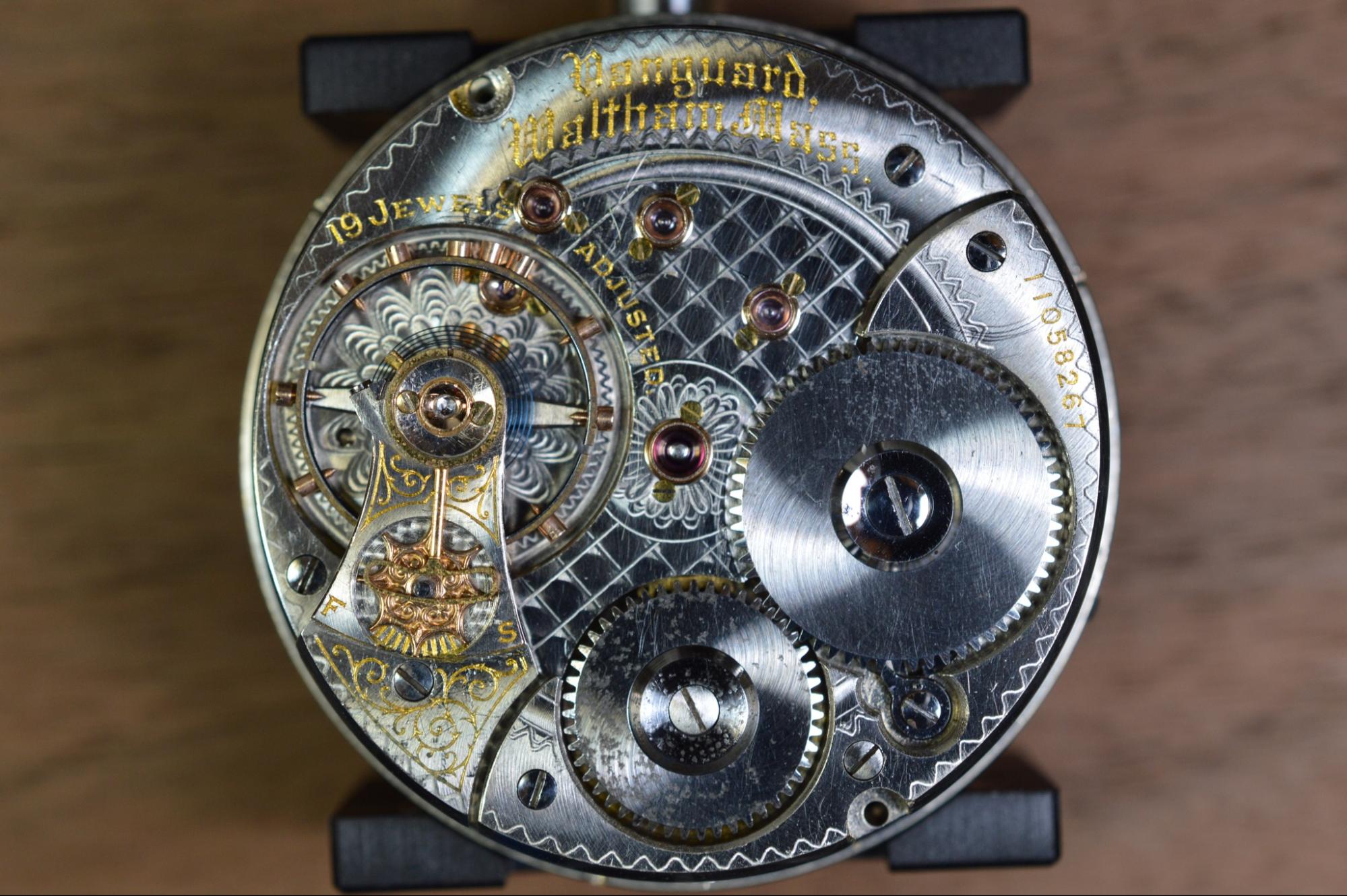
With all of the advantages of EDM for gear fabrication, there are some cool applications out there. From micro machining gears for watches and clocks to more robust gears like used on race cars, wire EDM and sinker EDM can be valuable despite its slow speed in comparison with other machining methods.

We hope this article helped you to understand gears fabrication using EDM. Consider adding our EDM service to your existing choice of manufacturing processes. Create an account with Fictiv to upload your gear design and see how we can work with you on your EDM process.


