Time to read: 4 min
Design for Manufacturing (DFM) is a critical component of product development that can make or break your product design. It can be integrated early and often in the process as design revisions are made, ensuring the designer and manufacturer are aligned. However, it can often be more complex and time-consuming than expected.
At this stage in the FictivMade multi-tool phone stand project, I have designed and prototyped the product, submitted a quote for manufacturing, and received initial automated DFM feedback on the Fictiv Platform. Next, I’ll review the post-sale DFM feedback in more detail, including decisions about necessary design changes.
DFM Overview
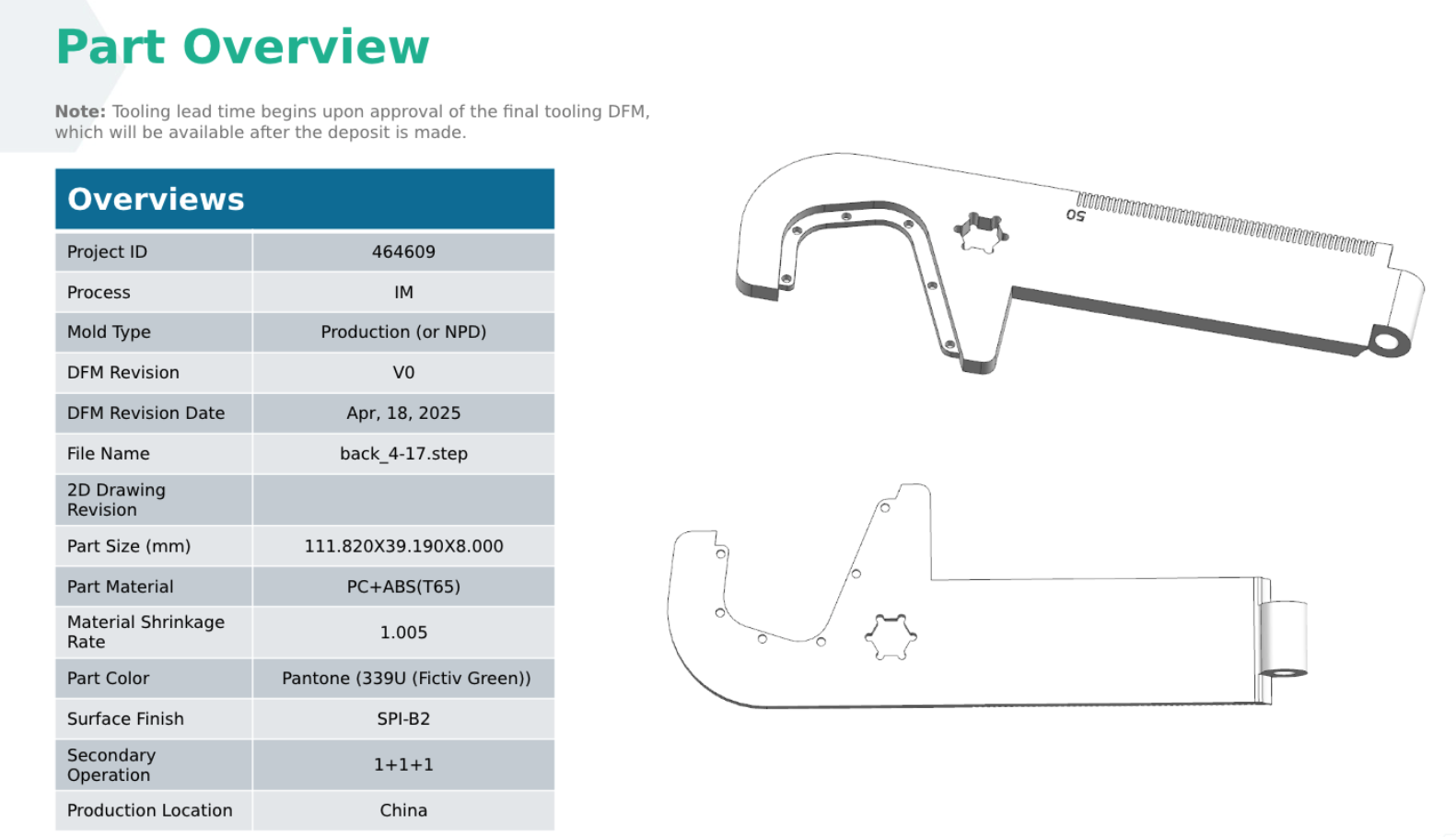
Full DFM feedback is often presented in a PowerPoint slide deck that includes detailed feedback for each part. The first slide for this component provides an overview of the part, confirming details such as material, color, and surface finish.
Parting Lines
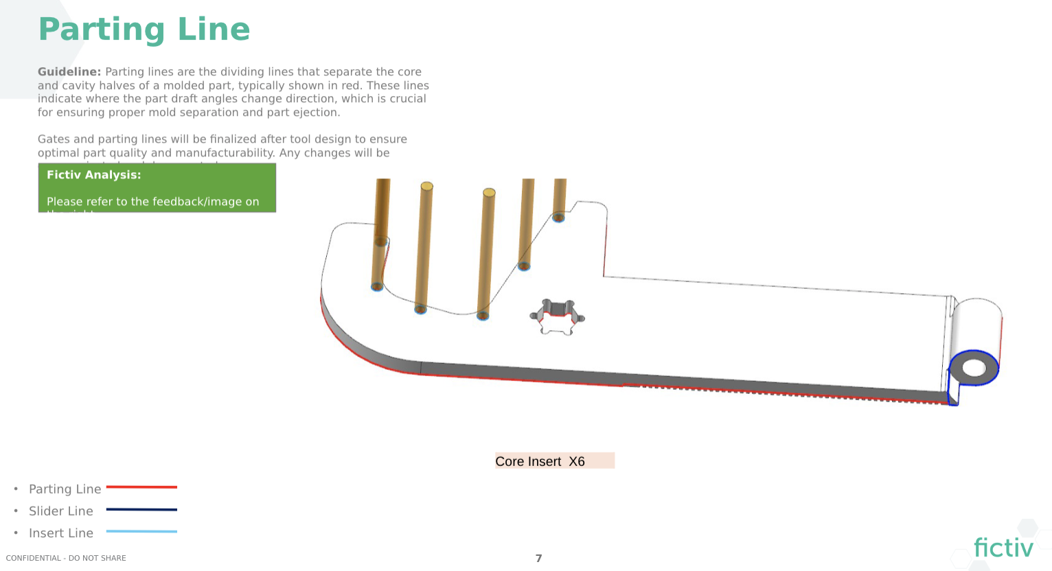
Multiple images show the parting lines around the entire part, including core insert pins to create the holes in the overmold rib, and slides to create the undercut hole in the hinge.
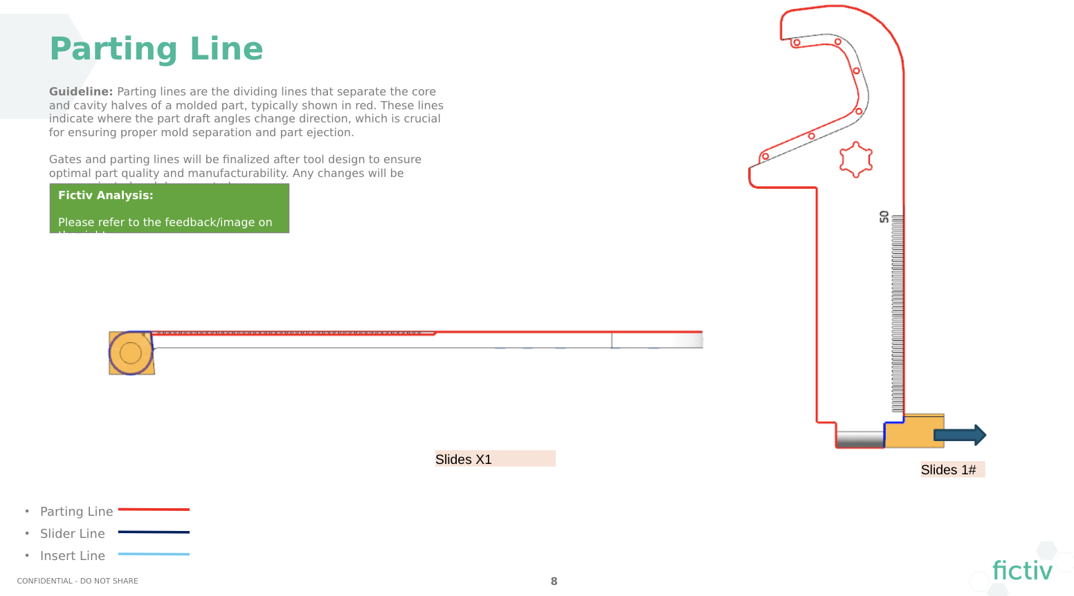
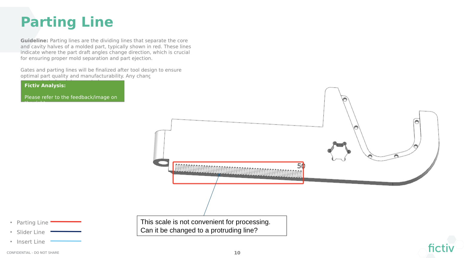
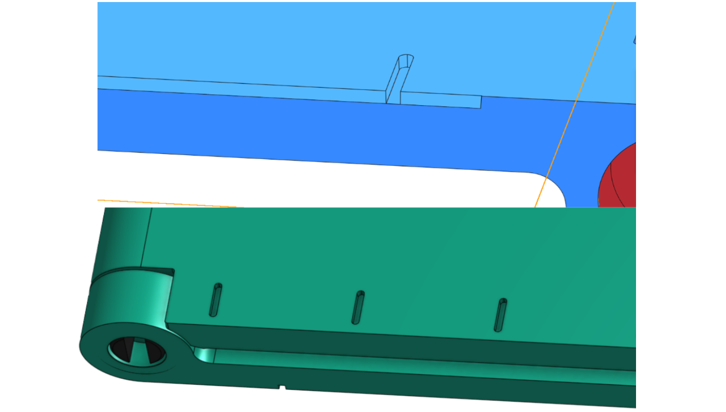
One piece of feedback was that the millimeter markings were too close together, as shown below. Our manufacturing partner suggested protruding rather than recessed lines, but I wanted the part to be able to lie flat on a surface. Instead, I changed them to centimeter marks and inset them from the edge for a simpler parting line.
Gate Location
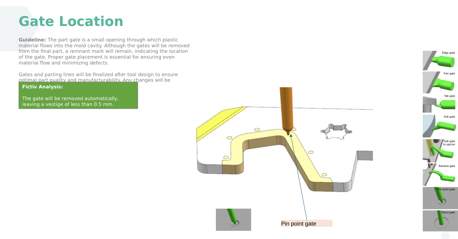
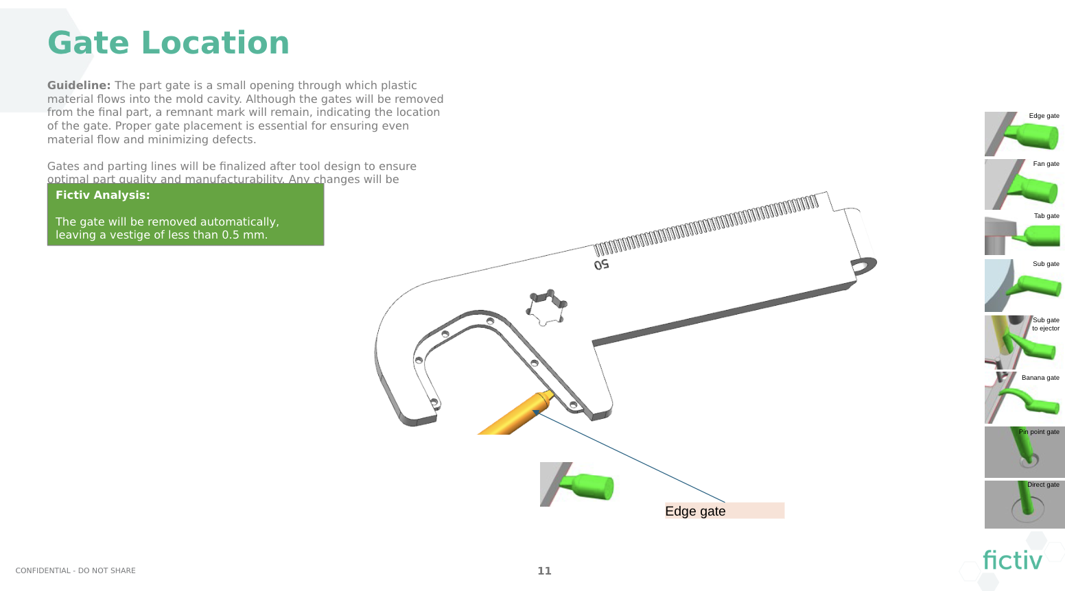
The DFM shows the gate locations, which I approved. There is an edge gate for the front part that is covered by the TPU overmold, and a more minimal pin point gate for the TPU overmold itself. There are various pros and cons to different gating options based on how visible you want the gate vestige to be on the part, and what is allowable for proper material flow.
Weld Lines
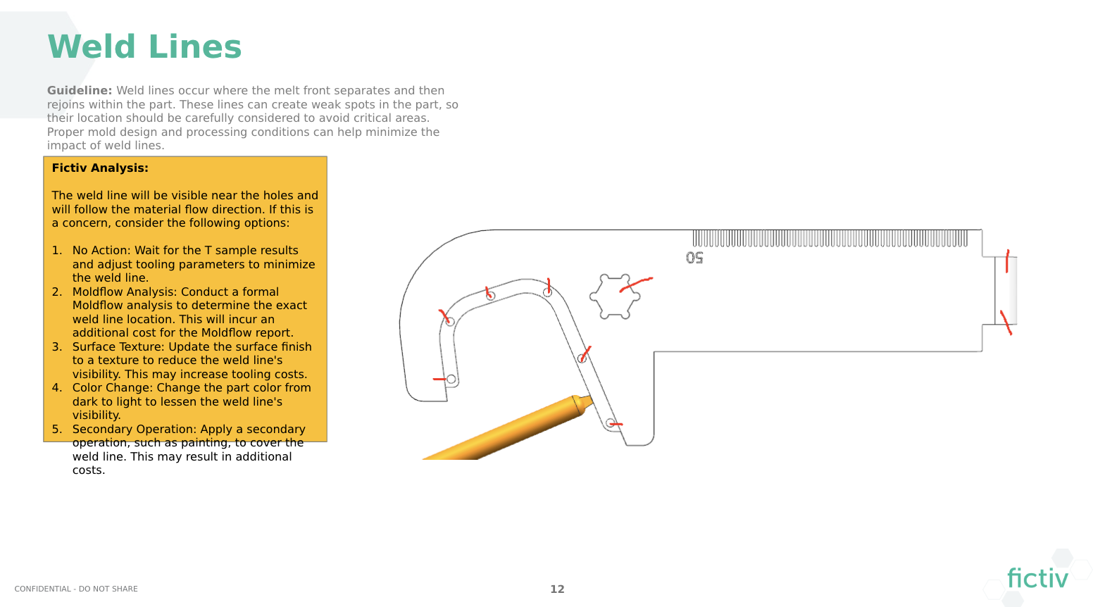
Our manufacturing partner pointed out that weld lines might form around the holes in the part, which was a valid concern. However, I kept these features unchanged because they’re essential for functionality. Although a minor weld line could appear outside the hex recess hole, we optimized the gate location to help reduce this risk.
Ejection Pins
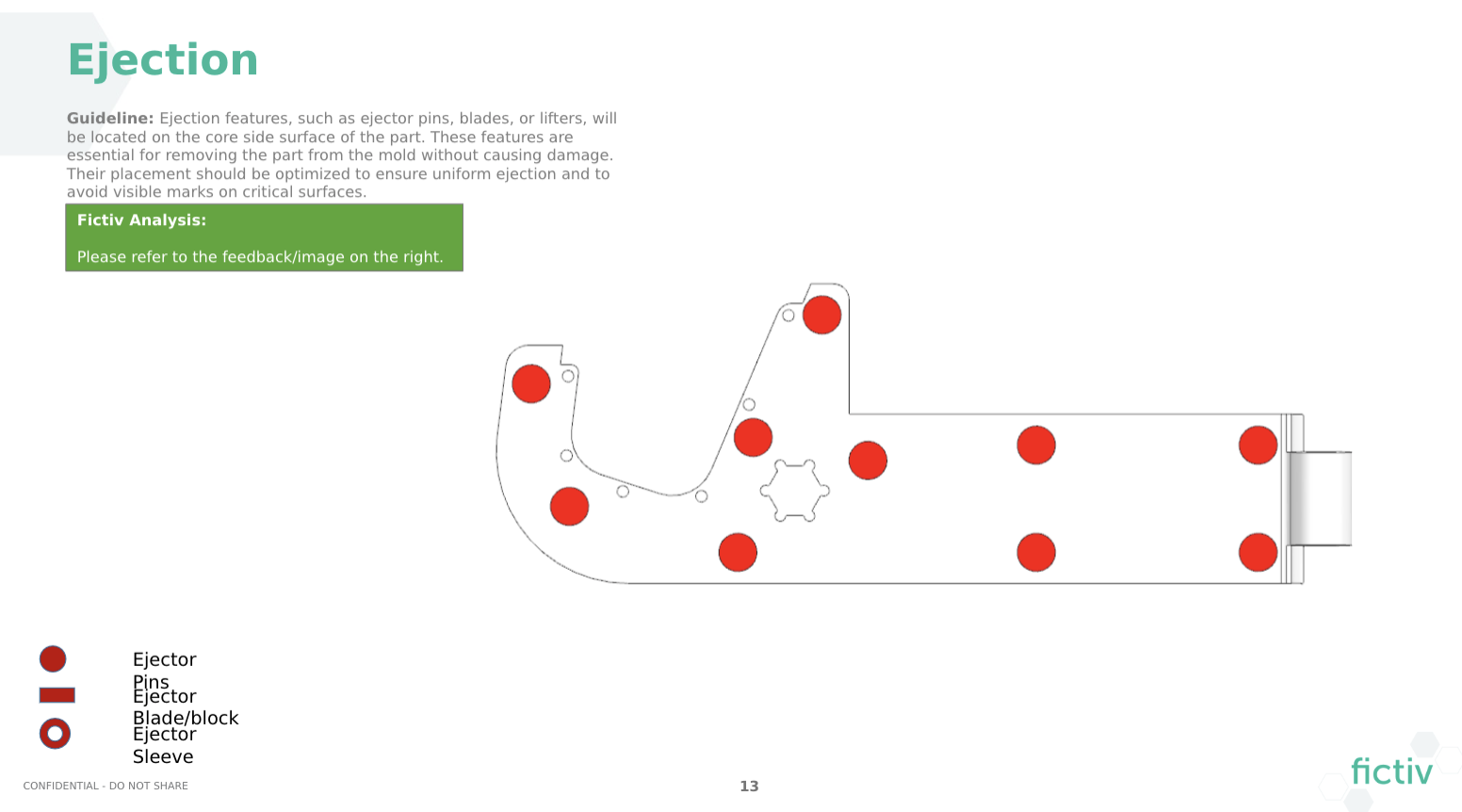
The DFM showed the ejector pin (and mark) locations on the interior of the part. I wasn’t sure it was necessary to have this many EJ (ejector) pins, but I accepted it because it’s a less visible B surface. In cases where aesthetics are more of a concern, there are ways to reduce EJ pins, such as an ejector block or manual removal of the part (though this can increase the risk of defects, such as warping).
Draft Analysis
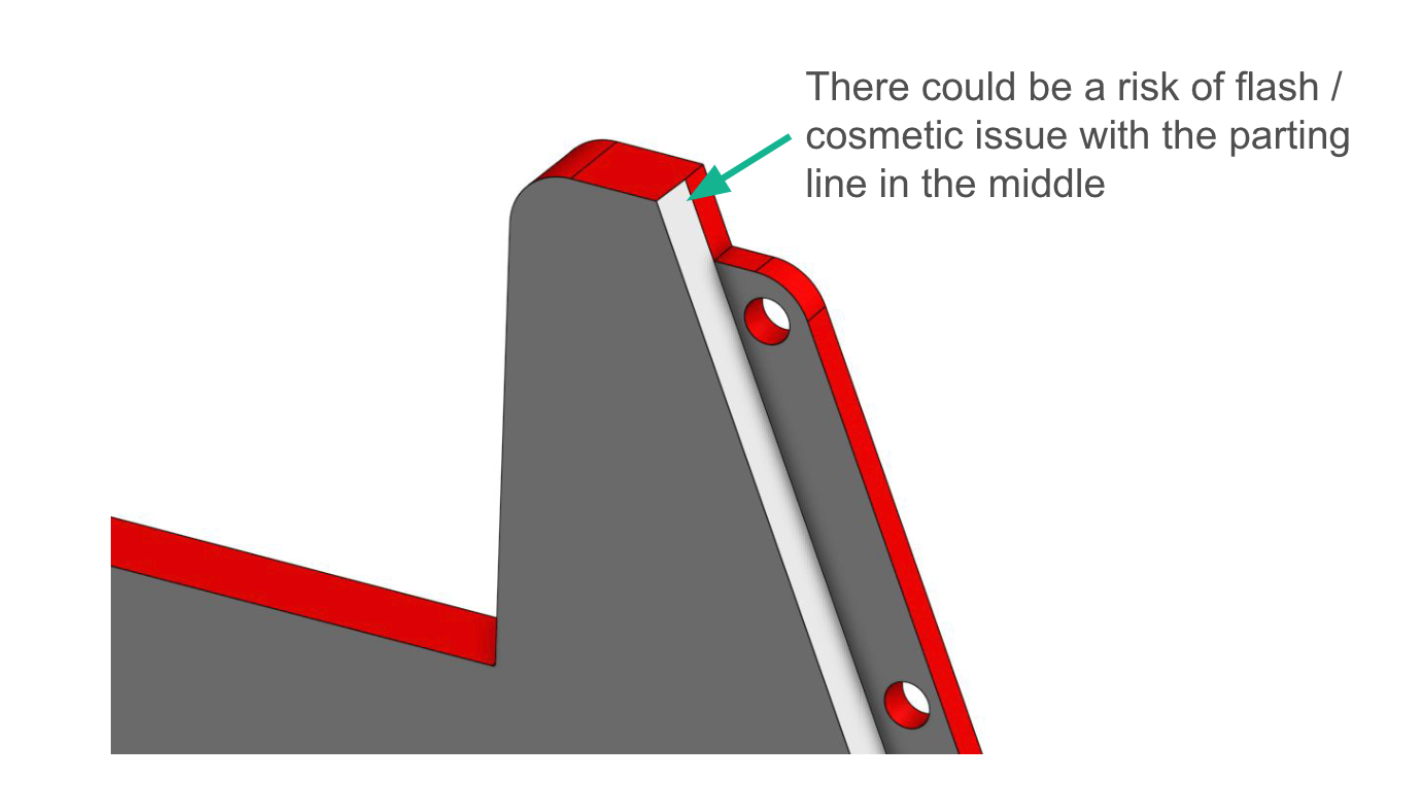
One significant change suggested was to modify the draft direction (and parting line), particularly in the overmold area, which would move the rib to the internal side of the part. Initially, I wanted to hide the rib entirely within the TPU—but Felix Zhang, Manufacturing Engineer for injection molding, recommended this change to facilitate demolding. I agreed, figuring it might be visually interesting to showcase the mechanical fastening features on the interior.
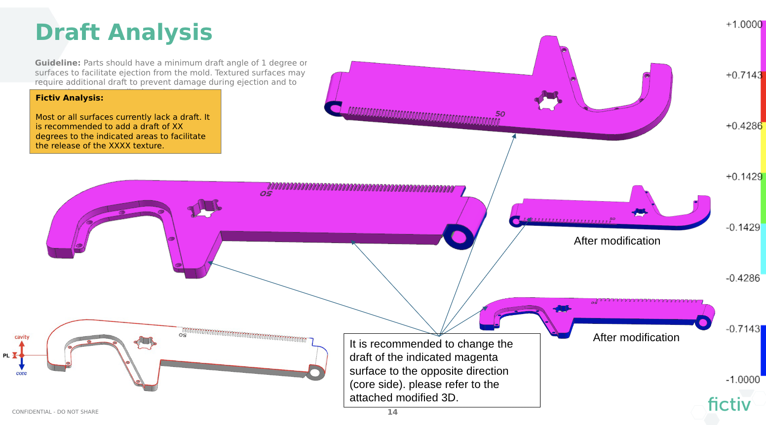
However, I highlighted the risk of flash and mismatch at the parting line. I was correct that this was a concern with the TPU overmold, but it was solvable by trimming the flash.
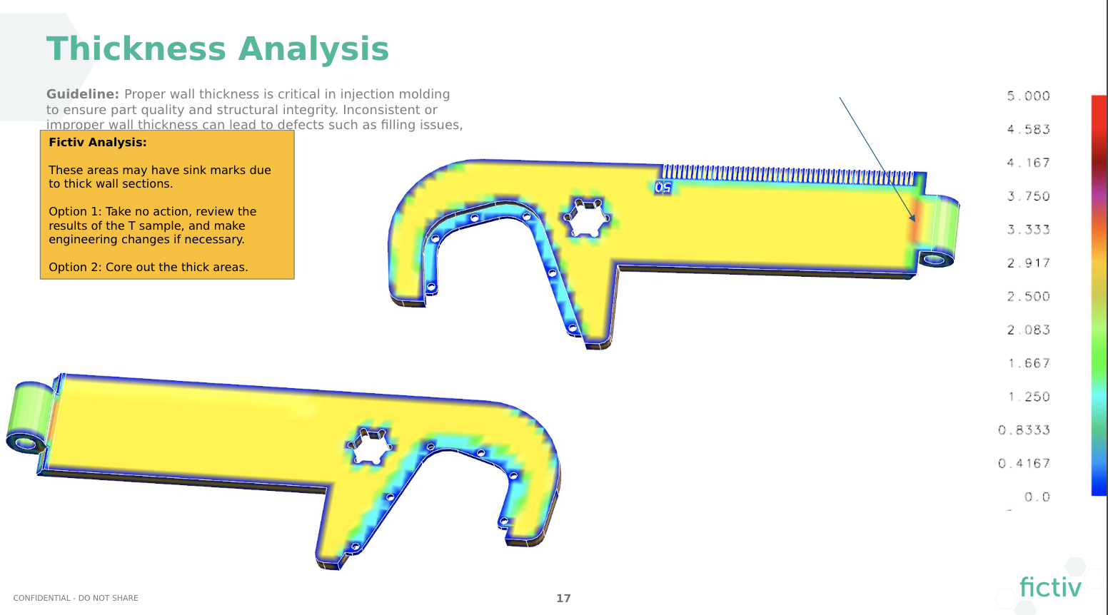
Wall Thickness and Sink Concerns
When evaluating wall thickness, there was a risk of sink in the thicker section by the hinge. I had used a fillet to remove the undercut underneath the circular hinge, but it added thickness to that area. I moved forward with the risk, because it was a gradual transition, and therefore sink could likely be processed out.
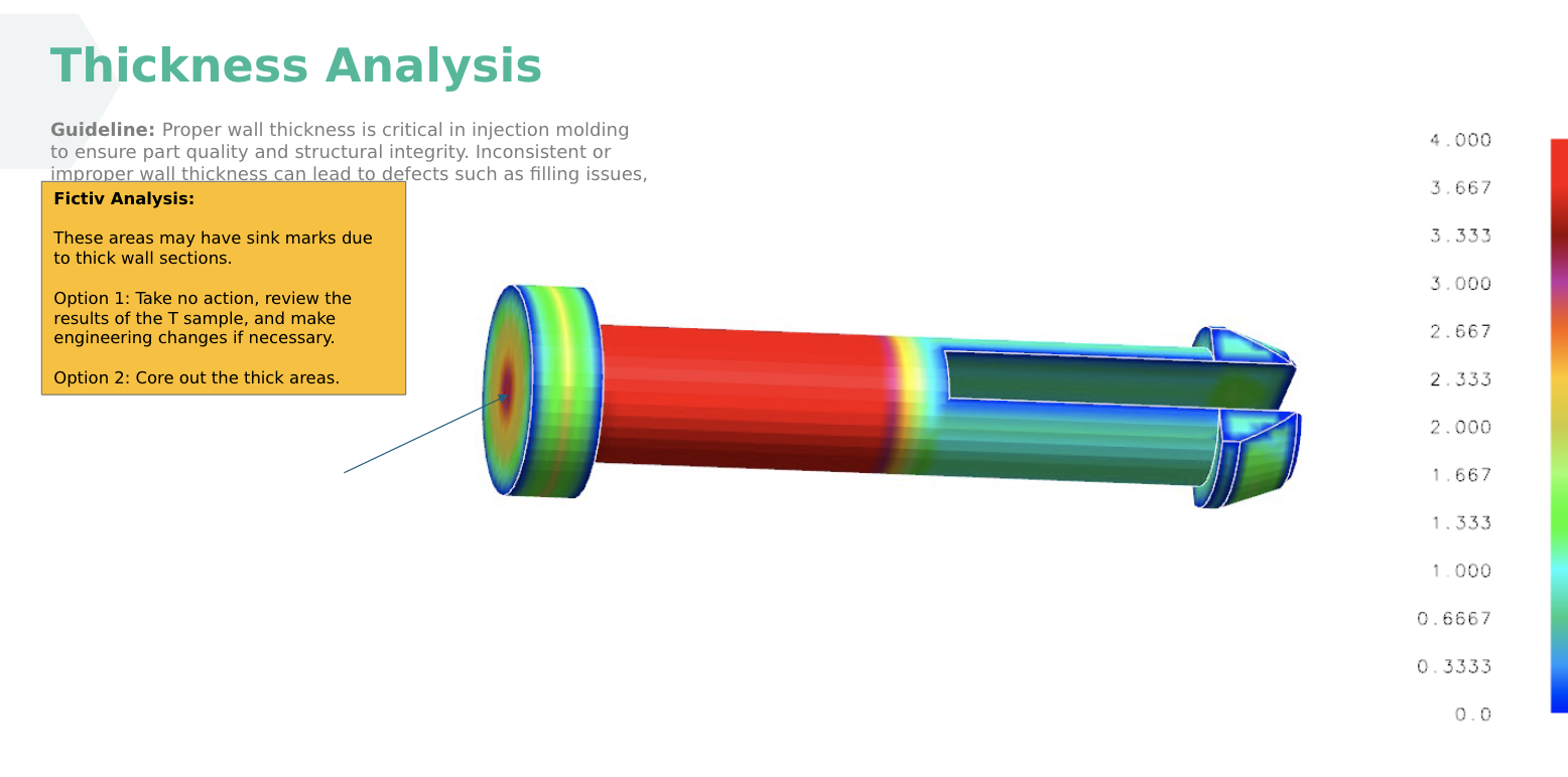
For the hinge pin, maintaining the nominal thickness proved more difficult. I had to add material to stiffen the pin snap, making it thicker in that area. I suggested adding a heavier texture to the outer head of the pin to hide the sink.
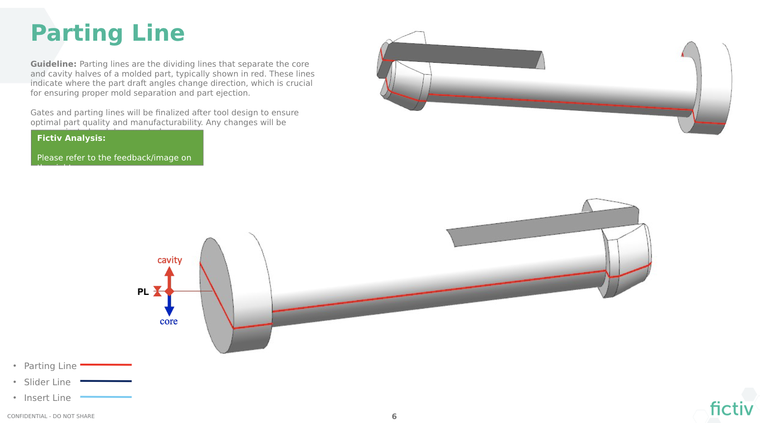
This fix became a challenge due to the way the draft was split, creating a parting line in the middle that was visible on the relatively flat outer surface. A heavier matte texture could hide the sink, but may cause drag marks if the draft wasn’t increased.
Prototype to Production Changes
It’s important to make any design changes to prototype-specific features that are unnecessary for production or would complicate the tooling.
For the hex recess, I removed the corner core-outs for CNC machining and changed them to simple, sharper corners, while maintaining proper clearance for a hex bit. If 3D printing is used for the prototype, a detailed design review is helpful to make sure it is moldable.

Logo Treatment: Gloss Finish vs. Pad Printing
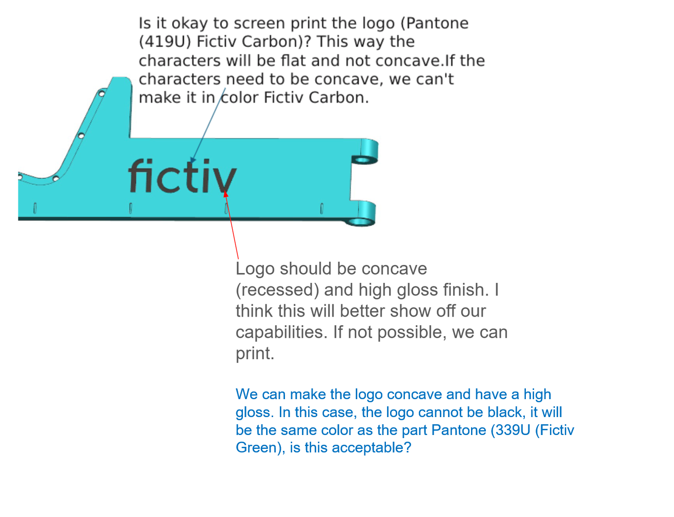
Features such as surface finishes and post-processing steps, like printed logos, often require additional back-and-forth. In this case, I was debating a black Fictiv logo but decided to move forward with a recessed logo with a polished finish. We had the option to add plastic steel-safe and pad print the logo on a flat surface if we ever wanted to change the color to black.
This is why it is so important to have clear communication and reliable manufacturing partners. Even if you put a lot of time and effort into designing the part for manufacturability before the DFM review process, there will always be changes requested that you will have to prepare for and decide on.
Project Timeline
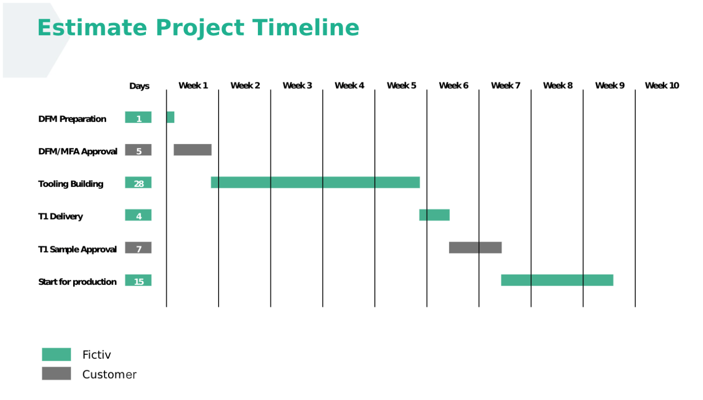
A simple Gantt chart in the DFM deck shows the mold and part production timeline. This can also be tracked closely in our Mold Library.
Ready to Bring Your Own Concept to Life?
Turn your product idea into a manufacturable reality with expert design support and a global supply chain built to scale.


