Time to read: 6 min
Parting line injection molding isn’t a special type of plastic injection molding or liquid silicone rubber injection molding. Instead, it’s used to minimize the appearance of witness lines—unavoidable marks on the surface of a part that show where the two halves of an injection mold come together.
Parting line injection molding is about minimizing flash—excess material that forms on the surface of parts. It’s also about determining where to add part features because molten plastic shrinks when it cools. If designers don’t consider the line of draw where mold halves separate, functional features might not work as planned.
Keep reading to learn more about parting lines in injection molding. You’ll also discover what designers are doing to get complex parts at amazing speeds. This article begins with some basics and then covers parting line locations, types, and the importance of working with a skilled injection molder.

What is the parting line in injection molding?
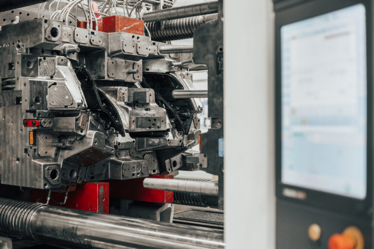
Injection molds have a core and a cavity. The parting line is where these two mold halves separate after an injection molding cycle is complete. It’s also where the two halves meet again when they’re clamped together before the next fill cycle.
- The mold cavity is concave so that it can be filled with molten plastic. It’s machined so that it’s a negative image of the exterior surface of the finished part.
- The mold core is raised or convex. It comes together with the mold cavity and produces the hollow interior features of the finished part.

For an example of how the core and cavity work together, consider the example of a plastic cup. The cavity shapes the exterior features of the cup that you hold in your hand. The mold core creates the hollow inside of the cup.
When the two halves of the injection mold come together, some of the core protrudes into the cavity and displaces plastic that would otherwise fill the cup. Typically, the mold parting line is located along the cup outer edge; however, you might not even notice the witness line there.
Both the core and the cavity have an important role to play, but there are some special considerations involving part ejection. The core is the bottom half of the mold and typically attaches to a moving clamp on the injection molding machine. This clamp has an actuator that controls ejector pins.
In turn, these metal action pins push against the surface of the molded part to release it from the tool. Because the ejection process usually leaves a mark, it’s better for the pins to contact a part surface – such as the bottom of a coffee cup – that’s usually unseen. For designers, this is just one of many aesthetic considerations.

Why does parting line location matter?
When you work with Fictiv, our design for manufacturability (DFM) experts can alert you to issues such as potential marks from ejector pins. We’ll also work with you on parting line location because of its relationship to the mold core and the mold cavity.
Sometimes, a parting line runs down the middle, such as the plastic handle of a tool. That might seem simple enough, but the parting line is also a borderline where draft—an angle that’s applied to vertical walls to aid in part removal—changes direction. In other words, the draft runs in one direction on one side of the parting line and in the opposite direction on the other.

With complex parts, a parting line can be hidden under a protruding feature such as a rim, button, or cap. On a plastic coffee cup, the parting line might run along the midpoint of the handle. That’s a nice way to minimize witness line appearance, but the handle still needs to be molded well enough so that any protruding plastic isn’t uncomfortable to the touch.
Fictiv can suggest the optimum parting line location when you request a quote and upload a 3D CAD model of your part – even if it lacks draft. If you’re using a CAD application like SolidWorks, you can apply your own draft angles and generate a parting line. It’s important to think about the parting line during your design, but remember help is available if you need it.
Regardless of your approach, there are three reasons why parting line location matters to your design: draft, flash, and costs.

Draft
The location of the parting line determines the location and direction of drafting features. Consider the example of a plastic container with straight walls. An injection molder could use a straight push-pull mold to separate the core and cavity. However, the mold would also need ejection mechanisms, called side actions, so the part won’t get “stuck” during ejection.
By applying draft to the vertical walls, the designer can eliminate the need for additional release mechanisms. Yet the designer must also account for how the mold separates since the draft runs in different directions on each side of the parting line.
Flash
Parting line location also determines the location of mold flash. If the two halves of a mold don’t align properly, molten plastic can escape. Flash can also emerge between ejector pins and their holes. Shutoffs, features that need extra draft, can also produce flashing.
Some amount of flash (i.e., the witness line) is expected, but excessive parting line flash in injection molding can detract from a part’s surface finish and visual quality. Flash can also interfere with seating, sealing, and part assembly. Mold quality is especially important. If a mold tolerance is inaccurate, there may be gaps where molten plastic leaks.

Costs
Adding side actions to molds and removing flash from parts adds costs. Some part designs, such as those that include necessary undercuts, require side actions due to design complexity. If a molded part has excessive flashing, a secondary process such as cryogenic deflashing may be required.
By following part design best practices, you can avoid or minimize other potential problems. Fictiv’s free “Injection Molding Design Guide” contains sound advice and takes a step-by-step approach to injection molding design.
Download the Injection Molding Design Guide
Types of Parting Lines in Injection Molding
Now that you’ve learned some parting line basics, it’s time to examine the different types of parting lines that can be used in plastic injection molding. The shape, function, and structure of your part usually determine the type of parting line required.
Vertical Parting Lines
Vertical parting lines are the most basic type and the most popular type. When the mold is machined, the vertical parting line is perpendicular to the direction in which the mold opens. Consider the example of a Lego block, a part that’s injection molded. The vertical parting lines are along the outside edges.

Beveled Parting Lines
Beveled parting lines have sloping edges instead of straight ones. They can help to reduce flash formation, but they’re generally reserved for more intricate molds. For example, a rib can be beveled at the top to avoid trapping air. If the rib is where the two halves of the mold separate, a beveled parting line may be used.
Curved Parting Lines
Curved parting lines are used with curved parts, or where some of the parting line runs along a curved surface. For example, an injection-molded drill housing might need a curved parting line to accommodate the area where the trigger, or button, is located.
Stepped Part Lines
Stepped parting lines are used when there’s such a large force on one side of the cavity that the mold halves could move or slide. Using a wedge-shaped insert on one side of the cavity can offload some of this force.
Comprehensive Parting Lines
Comprehensive parting lines incorporate the features of vertical, beveled, curved, and stepped parting lines. They’re especially intricate and are used mainly with very complex parts.

What Else Do Designers Need to Know about Parting Line Injection Molding?
To avoid parting line problems, injection molders must pay close attention to mold cooling rate, mold shearing rate, and mold stress factors that can affect core and cavity alignment. Sometimes, flash escapes along the parting line because of inadequate clamping pressure or venting. There could be mold flow issues as well.
It’s challenging enough to design the perfect injection molded part, but Fictiv combines expert DFM assistance with access to our network of skilled injection molders. Are you ready to put what you’ve learned about parting line injection molding into action and get complex parts at amazing speeds? Then create a free Fictiv account and upload your part drawing.