Time to read: 6 min
In mechanical engineering, creep is a metallurgical phenomenon where a metal slowly deforms due to prolonged exposure to stress below its yield strength. Read on to learn more about creep and how it works, then see some visual creep depictions and examples.
What is Mechanical Creep?
In Engineering Fundamentals Refresh: Strength vs. Stiffness vs. Hardness, we discussed the yield strength of a material — which defines the yield stress or the stress when a material will no longer elastically deform. When a material is subjected to its yield stress (or greater stress), it will plastically (permanently) deform, in principle. But a unique phenomenon occurs when the homologous temperature ratio of a material is equal to or greater than approximately 0.4. In that case, material can plastically deform slowly and progressively even if the applied stress is lower than the material’s yield stress.
Here’s how you determine the homologous temperature:

When a material is exposed to a temperature at least 40% as high as the melting temperature of the material, it’s more susceptible to deformation when exposed to stress below the yield stress of the material. This plastic deformation happens slowly over time, and it’s known as creep or ‘cold flow’.
Temperature influences creep because the material’s diffusivity — the ease with which the atoms within the material can move to vacant sites within the crystal lattice — increases near the material’s melting point. Creep is more likely to occur when materials have a higher diffusivity, so the likelihood of creep at a specific temperature for two different metals is different.

What Does Creep Look Like on the Atomic Level: Microstructure?
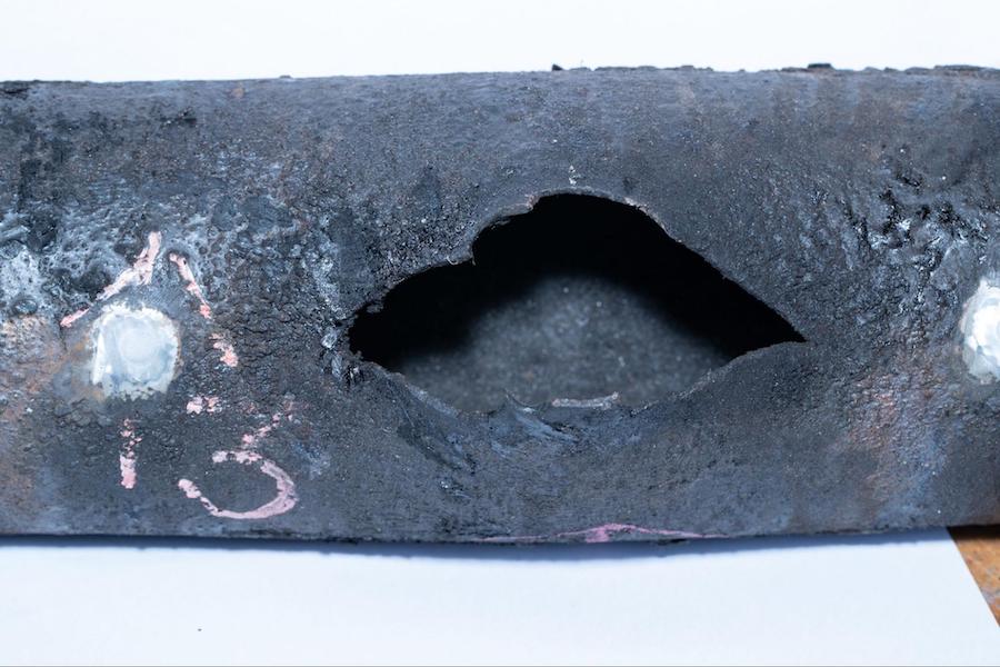
Creep on the atomic level occurs because of grain boundary sliding, or when adjacent grains move — which is more likely to happen when the diffusivity of a material increases. When cross-sectioning a part, the tell-tale sign of creep failure is that there is no obvious deformation of the grains directly at the fracture edge. Instead, you’ll see slippage of the grain boundaries in the proximity.
You’ll typically also see voids or pores in the microstructure cross-section, which are generally present at the location of nonmetallic impurities in the metal. (Such impurities are common, acceptable, and unavoidable, by the way.) These areas grow and join together to form cracks several grains long, and eventually those cracks fracture and fail.
So, it’s a good idea to choose materials with larger grain sizes to minimize the likelihood of creep. Doing so reduces the possibility of creep fracture by reducing the percentage of the material covered by grain boundaries instead of grains. So, look for materials with a coarser grain structure and be mindful of their homologous temperature ratio for the maximum operating temperature the materials will be exposed to.
Phases of Mechanical Creep: Creep Graph
As there are stress vs strain graphs for materials in which we find the yield strength, ultimate tensile strength, and failure point, there are similar graphs for mechanical creep. These creep graphs show that mechanical creep happens in three stages: primary, secondary, and tertiary.
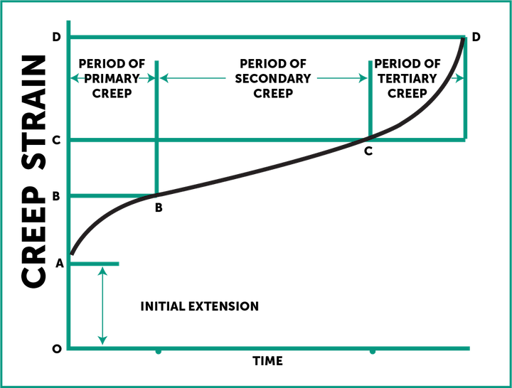
Here’s an explanation of the graph and creep phases:
- In the initial extension, from point O to A on the y-axis, the applied stress isn’t significant enough to cause creep and there is no measurable deformation of the test piece.
- Primary creep, from point A to B on the y-axis, is a transition where the rate of creep and deformation of the material decreases over time (slope decreases as time goes on).
- A constant, linear creep rate characterizes secondary creep, from point B to C on the y-axis. This creep phase can last a while — sometimes 10+ years.
- Tertiary creep is the final phase, from point C to D on the y-axis, that involves a rapidly increasing creep rate until material failure. During this period, the effective stress on the material increases due to microstructure changes within the material, and results in permanent deformation.
Calculating the Impact of Mechanical Creep on Your Design
To see if your CNC machined parts will be impacted by creep deformation, we need to go back to the basics of Constitutive Laws or Constitutive Equations. These laws dictate the amount of strain that is in a component versus the amount of stress it is exposed to. And these constitutive laws can be used to predict how your part will behave. There are a few variables for the constitutional laws of creep that you should concern yourself with, including:
- Q = activation energy; the amount of energy needed before creep may happen (in the case of creep, this is thermal energy)
- n = stress exponent; this is measured over the range of applied stress and determines whether or not you should expect to see pure diffusional creep or dislocation creep for the specific applied stress and temperature exposure your part sees, with the following ranges for each type of creep:
- For n approximately equal to 1-2, you should expect to see pure diffusional creep which is often termed Nabarro-Herring creep (N-H creep). This type of creep is where the diffusion mechanism is within the crystal lattice of the grains, rather than the grain boundaries. The activation energy for this type of creep is higher and the diffusion rate is low, and N-H is more frequently seen at high temperatures and for materials with larger sized grains or single crystal lattices.
- Note: Coble creep is a term used to describe diffusional creep where fast diffusion paths form along grain boundaries, and atoms are redistributed, causing deformation.
- For n approximately equal to 3-6, you should instead expect to see dislocation creep, which occurs when the components are exposed to higher stresses that approach the yield stress, but are still below it. This type of deformation is due to macroscopic plasticity through dislocation glide in the form of absorption or emission of vacancies at the core of the atomic structure. Shear stress amongst the atoms causes the dislocations.
Pro-Tip: For design tips and tricks for your next CNC part, check out our CNC Design Guide.
Calculating Creep Strain Rate for Linear (Secondary) Creep
Secondary creep is typically the predominant creep mechanism over time, and below is the equation to determine the creep strain rate for secondary creep. (Note: By creep strain rate, I mean the acceleration or rate of change of the von Mises strain, which in this case is plastic strain causing plastic deformation).
So, we have the rate of creep strain or the derivative of creep strain:
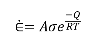
where: 𝜀˙= rate of creep strain (derivative of creep strain)
A = a constant based on the applied stress
Q = activation energy
R = universal gas constant
T = absolute temperature
Now, if you remember Calculus, you know that you can get a cumulative value for the creep strain that your design will experience over time by integrating both sides with respect to time. Here’s a head start for you.
Calculating Creep Strain Rate for Primary and Secondary Creep
If you’re looking for a single equation that can determine the impact of primary and secondary creep, look no further than the Miller-Norton Law. This law also covers the gray area of the transition between primary and secondary creep.

All the variables and utilization for this equation can be found here.
Key Takeaways About Mechanical Creep
- Mechanical creep occurs due to elevated temperature (at least 40% of melting temperature) and stress exposure near the yield stress of a material.
- Mechanical creep may take years of slow deformation before a material fails completely.
- To reduce the likelihood of creep failure, choose a metal with a higher melting temperature and/or larger grain size.
- Tertiary creep is brought on due to rising true stress (or stress that exceeds yield stress) or microstructural changes like cavitation that cause fracturing.
- Creep is time-dependent deformation, whereas conventional plastic deformation is instantaneous.
- Choosing single-crystal materials like Nickel superalloy increases creep resistance.
Fictiv – Let’s Build Something Great, Together
When it comes to picking the right materials to make your next CNC machining project impervious to mechanical creep, Fictiv has you covered.
We’re your operating system for custom manufacturing that makes part procurement faster, easier, and more efficient — our incredibly skilled machinists can deliver CNC machined parts in as fast as a day or two! So create an account and upload your part to see what our instant online CNC quote process, design for manufacturability feedback, and intelligent platform can do for you.


