Time to read: 12 min
The Finite Element Method (FEM) is a numerical analysis technique used to obtain approximate solutions to complex engineering and mathematical problems. It involves dividing a complicated object or system into smaller, more manageable parts, known as finite elements. These elements are connected together by nodes, and the governing equations for the entire system are expressed in terms of the behavior of these individual elements.
FEA (Finite Element Analysis) is the application of the FEM to a physical system in order to determine its behavior under various conditions. FEA is widely used in the fields of engineering, physics, and mathematics to model and analyze complex systems.
The FEA process typically involves the following steps:
- Pre-processing: This step involves the creation of a 3D model of the system using specialized software. The model is then divided into finite elements, and the material properties and boundary conditions for each element are specified.
- Analysis: In this step, the FEM equations are solved to obtain the response of the system to a specific set of conditions. This may involve solving for stresses, strains, displacements, or other physical quantities.
- Post-processing: Once the analysis is complete, the results are visualized and interpreted using specialized software. This step often involves creating animations, graphs, or other visual aids to help understand the behavior of the system.
Read on to learn more about the benefits and applications of FEA, the basics of FEM, and how they’re a part of high-performance computing.
FEA Benefits
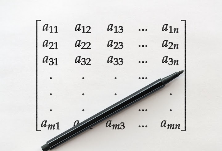
FEA has numerous advantages over traditional analytical methods, including the ability to model entire complex geometries and material behaviors at once, whereas traditional analysis methods are on a single point at a time. FEA also allows for the investigation of different design options and the prediction of the performance of a system under a wide range of conditions. However, FEA is a computationally intensive process, as you know if you have ever had to do one by hand — queue nightmares of manually resolving 100×100 matrices! As with many complex computations, the accuracy of the results is dependent on the quality of the model and the assumptions made during the analysis.
FEA can be used to analyze a wide variety of physical systems, such as structural components, heat transfer systems, fluid flow systems, and electromagnetics. Some common applications of FEA include analyzing the stress and strain in bridges, predicting the performance of airplane wings, and optimizing the design of medical implants.
FEA works by dividing a complex system into smaller, more manageable parts, known as finite elements. Each finite element is defined by a set of nodes and a mathematical function that describes the behavior of the element. The equations that govern the behavior of each element are then combined to create a system of equations that describes the behavior of the entire system.
FEA requires specialized software that is designed to handle the large number of equations and calculations involved in the analysis. This software typically includes tools for creating 3D models, specifying material properties and boundary conditions, solving the equations, and visualizing the results.
One of the main advantages of FEA is that it allows for the investigation of different design options and the prediction of the performance of a system under a wide range of conditions. This can help engineers and designers to optimize their designs and identify potential problems before building a physical prototype.
However, FEA has some limitations as well. For example, it relies on certain assumptions and simplifications about the behavior of the system being analyzed, and the accuracy of the results can be affected by errors in the input data or modeling assumptions. Additionally, FEA can be computationally intensive, and the time required to solve a complex analysis can be significant.
FEA Basics: Types of Elements
Different types of elements can be used in FEA to represent different shapes and geometries of structures, such as beams, plates, shells, and solids. Each type of element has its own set of equations and characteristics.
Structural Analysis
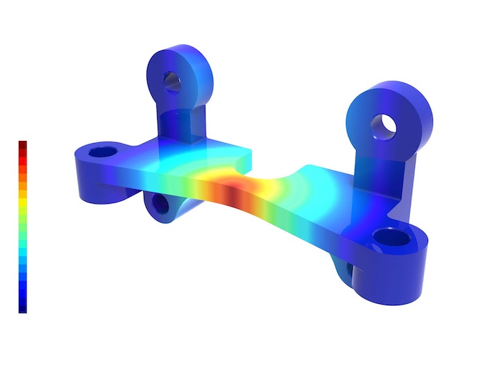
This type of FEA is used to study the behavior of structures under different loads, including static and dynamic loads, thermal loads, and fluid loads. The goal of structural analysis is to understand how structures behave when subjected to different forces, and to ensure that they can withstand these forces without failing or deforming beyond acceptable limits.
Structural analysis typically involves dividing a complex structure into smaller, simpler components, or finite elements, which can be modeled using mathematical equations. The behavior of each finite element is then analyzed and combined with other finite elements to create an overall picture of how the structure as a whole will behave under different loads.
There are several methods used in structural analysis, including:
- Finite element method (FEM): This method is widely used in structural analysis and involves dividing the structure into a mesh of smaller elements, each with its own set of equations.
- Finite difference method (FDM): This method is similar to FEM but uses a grid of points to divide the structure into smaller elements.
- Boundary element method (BEM): This method is used to analyze structures with complex boundary conditions and involves dividing the structure’s boundary into smaller elements.
Structural analysis is used in a wide range of fields, including aerospace, civil, mechanical, and materials engineering. It is used to design and optimize structures, to evaluate their performance under different loads, and to ensure that they meet safety and performance requirements.
Thermal Analysis
This type of FEA is used to study the behavior of structures and materials under different thermal conditions. The goal of thermal analysis is to understand how materials and structures will behave when exposed to different temperatures and how they will transfer heat to or from their surroundings.
Thermal analysis involves modeling the material or structure as a series of finite elements and analyzing the behavior of each element based on the temperature distribution and thermal properties of the material. The thermal properties of a material include its thermal conductivity, specific heat capacity, and thermal expansion coefficient.
There are several types of thermal analysis, including:
- Steady-state thermal analysis: This type of analysis is used to study the temperature distribution within a structure or material that is in a steady state, or in thermal equilibrium.
- Transient thermal analysis: This type of analysis is used to study the temperature distribution within a structure or material that is undergoing a change in temperature over time.
- Conjugate heat transfer analysis: This type of analysis is used to study the heat transfer between a solid material and a fluid, such as in a heat exchanger.
- Radiation heat transfer analysis: This type of analysis is used to study the transfer of heat through radiation, such as in a furnace or a spacecraft exposed to the sun.
Thermal analysis is used in a wide range of fields, including aerospace, automotive, electronics, and materials engineering. It’s used to design and optimize the thermal performance of structures and materials, to evaluate their behavior under different thermal conditions, and to ensure that they meet safety and performance requirements.
Fluid Analysis
This type of FEA is used to study the behavior of fluids, such as liquids and gases, within a given system. The goal of fluid analysis is to understand how fluids will behave under different conditions, such as pressure, flow rate, temperature, and turbulence.
Fluid analysis typically involves modeling the fluid as a continuum and dividing it into a mesh of smaller elements, which can be analyzed using mathematical equations. The behavior of each element is then combined with the others to create an overall picture of how the fluid will behave within the system.
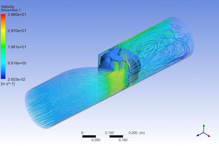
There are several types of fluid analysis, including:
- Computational fluid dynamics (CFD): This type of analysis is used to simulate fluid flow and heat transfer in a variety of systems, including pipes, valves, pumps, and turbines.
- Multiphase flow analysis: This type of analysis is used to study the behavior of fluids with multiple phases, such as liquids and gases, or liquids and solids.
- Acoustic analysis: This type of analysis is used to study the behavior of sound waves and their interactions with fluids, such as in the design of acoustic chambers and noise reduction systems.
Fluid analysis is used in a wide range of fields, including aerospace, automotive, chemical, and environmental engineering. It’s used to design and optimize the performance of fluid systems, to evaluate their behavior under different conditions, and to ensure that they meet safety and performance requirements.
Electromagnetic Analysis
This type of FEA is used to study the behavior of electromagnetic fields and their interactions with materials and structures. The goal of electromagnetic analysis is to understand how electromagnetic fields will behave in different systems, and to optimize the performance of devices that use or interact with electromagnetic fields.
Electromagnetic analysis typically involves modeling the electromagnetic fields as a set of mathematical equations, and the materials and structures as a series of finite elements. The behavior of each element is then analyzed and combined with the others to create an overall picture of how the electromagnetic fields will behave within the system.
There are several types of electromagnetic analysis, including:
- Magnetic field analysis: This type of analysis is used to study the behavior of magnetic fields, such as in electric motors, transformers, and magnetic sensors.
- Electric field analysis: This type of analysis is used to study the behavior of electric fields, such as in capacitors, transmission lines, and antennas.
- Electromagnetic wave analysis: This type of analysis is used to study the behavior of electromagnetic waves, such as in wireless communication systems, radar, and electromagnetic compatibility (EMC) testing.
Electromagnetic analysis is used in a wide range of fields, including electrical, electronics, telecommunications, and biomedical engineering. It is used to design and optimize the performance of electromagnetic devices and systems, to evaluate their behavior under different conditions, and to ensure that they meet safety and performance requirements.
Acoustic Analysis
This is a type of finite element analysis (FEA) used to study the behavior of sound waves and their interactions with materials and structures. The goal of acoustic analysis is to understand how sound waves will behave in different environments and to optimize the performance of devices that use or interact with sound waves.
Acoustic analysis typically involves modeling the sound waves as a set of mathematical equations, and the materials and structures as a series of finite elements. The behavior of each element is then analyzed and combined with the others to create an overall picture of how the sound waves will behave within the system.
There are several types of acoustic analysis, including:
- Structural acoustics: This type of analysis is used to study the transmission of sound waves through structures, such as walls, floors, and ceilings.
- Aeroacoustics: This type of analysis is used to study the generation and propagation of sound waves in fluid environments, such as in aircraft engines, turbines, and wind turbines.
- Vibroacoustic: This type of analysis is used to study the interaction of sound waves with mechanical vibrations, such as in the design of speakers and microphones.
Acoustic analysis is used in a wide range of fields, including aerospace, automotive, construction, and audio engineering. It is used to design and optimize the performance of acoustic devices and systems, to evaluate their behavior under different conditions, and to ensure that they meet safety and performance requirements.
Fatigue Analysis
Fatigue analysis is a type of finite element analysis (FEA) used to study the behavior of materials under cyclic loading. The goal of fatigue analysis is to understand how materials will behave under repeated loading and to determine their fatigue life or the number of cycles they can withstand before they fail.
Fatigue analysis typically involves modeling the material as a series of finite elements, and applying cyclic loads to the material over a period of time. The behavior of each element is then analyzed and combined with the others to create an overall picture of how the material will behave under cyclic loading.
There are several types of fatigue analysis, including:
- Stress-life fatigue analysis: This type of analysis is used to study the behavior of materials under constant amplitude cyclic loading, such as in the design of mechanical components subject to repetitive loading, like gears or springs.
- Strain-life fatigue analysis: This type of analysis is used to study the behavior of materials under variable amplitude cyclic loading, such as in the design of aircraft structures subject to various loads that are not always constant.
- Fracture mechanics: This type of analysis is used to study the behavior of materials with defects, such as cracks or notches, and how these defects can grow and lead to failure under cyclic loading.
Fatigue analysis is used in a wide range of fields, including aerospace, automotive, civil, and mechanical engineering. It is used to design and optimize the performance of materials and components subject to cyclic loading, to evaluate their behavior under different loading conditions, and to ensure that they meet safety and performance requirements.
Boundary Conditions
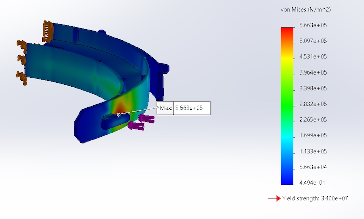
In FEA, boundary conditions are used to define the behavior of the system at its boundaries. They can include fixed constraints, applied loads, and other conditions that affect the behavior of the system.
Pro-Tip: Head over to this guide for setting up boundary conditions and analyzing the strength of a face shield headband in SOLIDWORKS:
Meshing
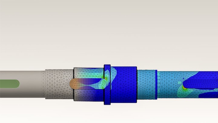
Meshing is the process of dividing the structure or system being analyzed into smaller elements. The size and shape of the elements can affect the accuracy and computational efficiency of the simulation.
Material Properties
FEA requires accurate input of the material properties of the system being analyzed, such as the elasticity and density of materials. These properties can be obtained from material testing or from published material data.
Convergence and Accuracy
FEA simulations can be iterative, meaning that the solution is refined until it converges to a stable solution. The accuracy of the solution depends on the mesh size, the order of the element, and the convergence criteria.
Dynamic Analysis
FEA can be used to analyze the dynamic behavior of systems, including vibrations and response to time-varying loads.
Pre-Processing and Post-Processing
The pre-processing stage involves defining the geometry, material properties, and boundary conditions of the system. The post-processing stage involves analyzing and interpreting the simulation results to draw conclusions and make recommendations.
FEM Basics
Solvers
FEM involves solving large systems of equations, which can be computationally intensive. There are different types of solvers that can be used to solve these equations, including direct and iterative methods.
Nonlinear Analysis
FEM can be used to analyze systems with nonlinear behavior, such as materials that exhibit plastic deformation or structures that undergo large deflections. Nonlinear analysis requires specialized techniques and algorithms.
Contact Analysis
FEM can be used to analyze systems that involve contact between surfaces, such as in mechanical systems or in biomedicine. Contact analysis requires specialized techniques to accurately model the behavior of contact interfaces.
Optimization
FEM can be used to optimize the design of structures and systems to meet specific performance criteria, such as minimizing weight or maximizing strength. Optimization requires specialized algorithms that can efficiently explore the design space.
Uncertainty Quantification
FEM can be used to assess the uncertainty and variability in the behavior of systems due to uncertainties in material properties, boundary conditions, and other factors. Uncertainty quantification requires specialized techniques and statistical methods.
Multiscale Modeling
FEM can be used to model systems that exhibit behavior at multiple length scales, such as in materials science or biomedicine. Multiscale modeling requires specialized techniques to accurately model the behavior of each length scale.
High-Performance Computing
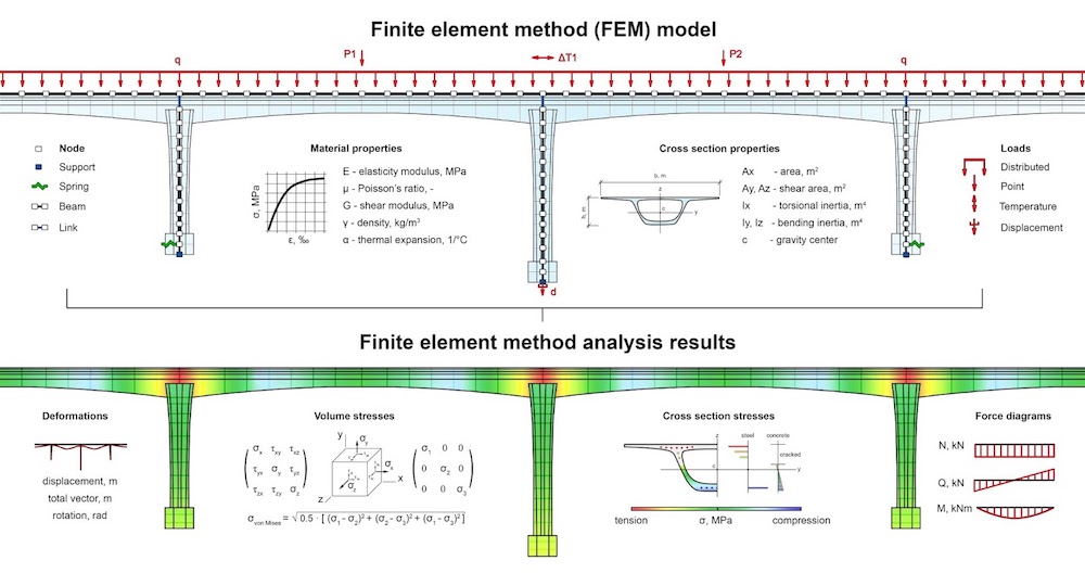
FEM simulations require significant computational resources and time, particularly for large and complex systems. High-performance computing can be used to accelerate FEM simulations and enable larger and more complex analyses.
Differences Between FEA and FEM
FEA (Finite Element Analysis) and FEM (Finite Element Method) are closely related concepts, and the terms are often used interchangeably. However, there are subtle differences between the two:
- FEM refers to the mathematical framework used to solve complex equations in engineering and mathematical applications. It involves dividing a complex system into small, simple elements that can be described mathematically. FEA, on the other hand, refers to the application of FEM to analyze physical systems and obtain approximate solutions to complex engineering problems.
- FEM can be used in a wide variety of fields, including physics, mathematics, and engineering, while FEA is specifically focused on the application of FEM to engineering problems.
- FEM is a purely mathematical concept, while FEA involves the use of specialized software and tools to create 3D models of physical systems, specify boundary conditions and material properties, and visualize the results.
- The terms FEM and FEA are often used interchangeably, but FEA is generally used to refer to the complete process of using FEM to analyze physical systems, while FEM is used more generally to refer to the mathematical framework itself.
In summary, FEM is a mathematical framework used to solve complex equations, while FEA is the practical application of FEM to analyze physical systems and obtain approximate solutions to engineering problems.
Complex Parts at Ridiculous Speeds – Start Your Next Project With Fictiv
If you’re trying to find a manufacturer to make your carefully analyzed and designed parts, Fictiv can help! Whether it’s injection molding, 3D printing, urethane casting, or CNC machining services, Fictiv is your operating system for custom mechanical parts. Our engineering experts can help you pick the right material for your application, and guide you through the manufacturing process so that you get great results.
Create an account and upload your design today to see what our instant quote process, DFM feedback, and intelligent platform can do for you — we deliver complex parts at ridiculous speeds!


