Time to read: 9 min
As a wee mechanical engineering intern working for a local steel manufacturing company, I will never forget the first time I stepped on the shop floor and saw plasma cutting in progress. It was the summer after my sophomore year, so I didn’t have much experience at that point, but I was mesmerized by the process. If you have ever been around plasma cutting, you may remember the sensory experience it provides: the bright flash of light, the sound reminiscent of many tig welding torches operating at once, and the unmistakable smell of burning metal mixed with burning gas that nearly hits your tongue it is so strong.
A common and useful manufacturing method, plasma cutting is a thermal cutting process that uses a high-temperature arc to melt flat sheets into various shapes. It can only work with conductive materials and can cut at high speeds while also being lower cost than laser cutting in terms of initial capital investment. Plasma cutting is often used for cutting, shaping, and gouging metal parts.
This article will describe in detail what plasma cutting is, how it works, the different types of plasma cutters, and the advantages and disadvantages of the technology.
What Is Plasma Cutting?
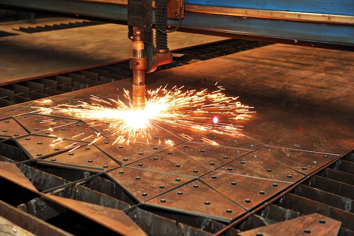
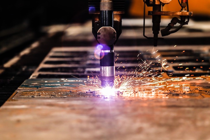
Plasma cutting refers to a thermal cutting technology designed to produce 2-dimensional profiles out of a thin sheet or plate made from a conductive material. Contrary to popular belief, plasma cutting is actually useful for producing complex cuts and complex parts and is especially well-suited for curves and circles. This complex shape-cutting ability is achieved by generating high-temperature plasma, which melts through the conductive metal while a drive system moves the plasma torch around the plate to trace out the required shape. In other words, the parts are held in shape while the cutting tool moves around the surface of the parts.
Hot molten slag is ejected from the cut using the compressed gas used to generate the plasma arc. Plasma cutters are often considered a less-expensive alternative to laser cutters but can still achieve good edge quality, especially with thinner sheets. For thicker sheets, the cut edge is not always as clean as with laser cutters. Plasma cutting is also an improvement over oxy-flame cutters in terms of edge quality and cut precision.
Only parts with a 2D profile can be cut on a standard computer numerically controlled (CNC) plasma cutter, but plasma cutting can be used to get a profile of a shape which is later refined with CNC machining. Therefore plasma cutting is often incorporated as a part of the overall CNC machining manufacturing process.
How Does a Plasma Cutter Work
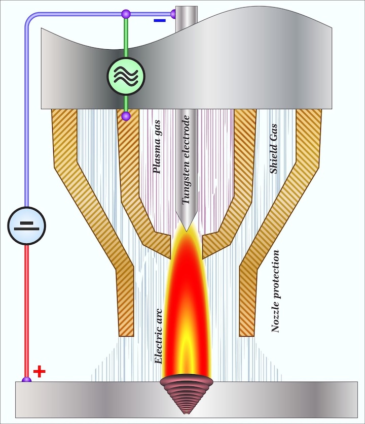
As the name implies, plasma cutters can cut metal sheets and plates by ejecting a high-temperature plasma from a nozzle. This plasma melts the metal by creating a narrow cutout called a kerf (also the term for the width of the cut made by the plasma arc). The plasma stream is created by heating a gas to the point at which the electrons are no longer bound to the nucleus of the atom. It consists of free electrons and positively charged atomic nuclei, i.e., ions. Plasma is often considered the fourth state of matter and is formed by heating gas to super high temperatures or exposing gas to a strong electromagnetic field which causes ionization of the gas atoms, which causes the generation of an electronic charge.
To create the plasma, an electric arc is created when a high voltage is introduced in an electrode that is situated inside the cutting head, known as a pilot arc. At the same time, a gas is introduced into the nozzle in the area between the electrode and the plasma torch body. As the gas contacts the arc, it is heated to the point where it becomes plasma. This plasma then flows down the cutting head and out of a nozzle. The arc follows the path of the plasma until it contacts the base metal. This allows the electric circuit to complete, and a constant arc is maintained, which ionizes new gas as it is fed through the nozzle. This is why plasma cutting is only compatible with conductive metals, like steel, stainless steel, aluminum, brass, and copper.
When the high-pressure plasma is directed out of a nozzle, there is an increase in its velocity, which helps eject the molten material from the cut. To contain the plasma in a tight circle, a shielding gas or liquid is ejected around the plasma nozzle, which keeps the plasma contained in a focused point for optimal accuracy. There are generally two types of arc generation techniques used with CNC plasma cutting, as described below:
- Pilot arc: The pilot arc method creates an electric arc inside the cutting head. This pilot arc creates some plasma that helps connect the arc to the workpiece as the highly conductive plasma flows through the nozzle. This method is most commonly used on CNC plasma cutters.
- High-frequency contact: A high-frequency spark is created when the nozzle touches the workpiece. Once a spark is generated and sufficient plasma has been created, the nozzle can be lifted, and cutting can commence.
Types of Plasma Cutters
There are many different plasma cutter designs available. While plasma cutters can be CNC or manual, most modern plasma cutters capable of achieving precision or tight tolerance parts are CNC plasma cutters. Within those classifications, most of the differences lie in how the nozzles are configured, what gas is used, and the chosen cooling method. Listed below are some common plasma cutters:
Conventional Plasma Cutting
Conventional plasma cutting typically uses a gas like argon or nitrogen to generate the plasma arc. This technique does not produce the highest quality but is cheaper to operate compared to water injection or dual gas systems. Air plasma cutting is a subset of conventional plasma cutting and uses normal air to generate the plasma arc. This technique is often used in low-production, entry-level systems as it is cheap and easy to operate; however, cut quality is poor.
High-Definition Plasma Cutting
Also called HTPAC (High Tolerance Plasma Arc Cutting), high-definition plasma cutting can produce cut edges whose quality is between standard plasma cutting and laser cutting, especially for thinner materials. This process constricts the plasma arc through various techniques, such as magnetic field confinement and improved nozzle gas flow. High-definition plasma is typically slower than laser cutting and conventional plasma cutting. The advanced HTPAC offers a more narrow kerf, results in tighter tolerances, ensures higher precision, and can even result in significant material savings.
Water Injection Plasma Cutting
In this process, water is radially introduced around the plasma arc. This constricts the plasma to create a reduced kerf, improved cut squareness, increased cutting speed, and significantly higher plasma temperatures. This technique must not be confused with water-shroud plasma cutting.
Water Shroud Plasma Cutting
Unlike water injection plasma cutting, this technique does not inject the water directly around the plasma arc but instead surrounds the arc with a cascading shroud of water. This technique does not improve the cut quality when compared to conventional plasma cutting but instead helps reduce noise levels and improves nozzle life by creating a barrier around the arc.
Dual Gas Plasma Cutting
This technique makes use of a primary plasma gas as well as a secondary gas shield that helps constrict the plasma arc, similar to water injection plasma cutting. This constriction improves cut quality and cut squareness. The secondary gas also helps blow out the molten slag during cutting which can result in reduced post-processing.
Main Components of a Plasma Cutter
Listed below are the standard components of a CNC plasma cutter:
- Plasma Torch: The torch is the primary component of a plasma cutter as it creates the plasma arc. The torch typically contains an electrode that creates and maintains the plasma arc. These can be water-cooled and allow for secondary gasses and fluids to be introduced to constrict the plasma arc, provide cooling, or reduce noise.
- CNC Controller: The CNC programmer turns a 2D design into machine-readable instructions called G-code. The CNC controller then converts the G-code into specific instructions for the stepper motors.
- Power Supply: The power supply converts an AC (alternating current) power source into a DC (direct current) power supply required to produce a continuous plasma arc. The power supply also provides voltage and current regulation to generate a stable plasma arc.
- Table: The bed is where sheet or plate material is supported during the cutting. In some cases, the bed allows the raw material to be submerged under a layer of water to reduce the noise created during the cutting process.
- Drive System: The drive system consists of drive motors that can either be stepper or servo motors. Next, linear drives like ball screws or toothed belts convert the rotational motion created by the motors into linear motion that moves the torch to trace out the design being cut based on the G-code created by the CNC programmer.
- Gas Supply: A constant gas supply is needed to generate a plasma arc. Different gasses, including normal air, argon, nitrogen, oxygen, and hydrogen, can be used. A secondary gas can also be introduced to help constrict the arc to improve cutting.
Using a CNC plasma cutter consists of multiple steps, generally listed here:
- The part is designed using a CAD (computer-aided design) package. The design is then saved in a .dxf file format. This file is then loaded into a CAM (computer-aided manufacturing) package that converts the .dxf into G-code, a set of instructions for the CNC controller to execute to produce the part.
Pro-Tip: For tips on starting your 3D model design, check out our guide 3D Modeling: From Fundamentals to Advanced Techniques.
- The material to be cut is selected. When designing your parts, it’s good to know that most production plasma cutters can accommodate standard sheet sizes; however, it may be required to cut the sheet smaller to fit on the plasma cutter – adding to costs. Check with your manufacturing partner to learn the maximum sheet size the plasma cutter can handle.
- Your manufacturing partner will always inspect the plasma cutter prior to operation. This is a critical step to ensure the safety of those making your parts.
- Your manufacturing partner will closely monitor the cutting to ensure that everything is proceeding as expected.
- Your parts will then be removed when the part the cutting is complete. There will usually be some slag attached to the cut edges that can be removed either with a slag hammer or by making use of a grinding wheel. Some manufacturing facilities have dedicated part cleaning operators to perform the tedious process of deburring parts.
Common Plasma Cut Materials
As a rule, plasma cutters only work on electrically conductive materials because the plasma needs to create an electrical connection between the torch and the raw material. The gas used to generate the plasma also depends on the material being cut. Plasma cutters can cut up to 150 mm thick plate, depending on several factors like the power rating of the machine and the arc coherence. Listed below are some common materials that can be cut using a plasma cutter:
- Aluminum
- Mild steel
- Stainless steel
- Brass
- Copper
- Cast iron
Plasma vs. Oxy-Fuel
The oxy-fuel process can cut material due to an oxidation process by burning the metal using a fuel like acetylene in the presence of oxygen. The high-pressure oxygen then blows out the molten slag from the cut. Oxy-fuel cutters are typically only used on easily oxidized materials like carbon steel and are not recommended for non-ferrous materials like copper or aluminum. Oxy-fuel cutters can cut materials up to 300 mm thick; however, the cut edge is poor compared to plasma cutting.
Advantages and Disadvantages of a Plasma Cutter
Table 1 below lists some common advantages and disadvantages of plasma cutters:
| Advantages | Disadvantages |
| Cheaper than comparable technologies like laser cutting. While they cannot produce the same level of quality, plasma cutters are a good alternative for small businesses. | It can only work with conductive materials as there needs to be an electrical circuit from the plasma torch through the plasma arc and into the raw material. |
| It can be used on a wide variety of metals as long as they are electrically conductive. This is in contrast to technologies like oxy-fuel cutters which cannot be used to cut materials like stainless steel. Plasma cutters can also cut highly reflective materials like copper or aluminum which can challenge some laser-cutting technologies. | Plasma cutting does not produce the best-cut edge and cannot cut highly precise designs that are possible with laser cutting. The plasma arc is wider than a laser, which results in a larger kerf that prevents plasma cutters from being used to cut fine-featured, intricate parts. |
| It can cut some conductive materials much quicker than laser or oxy-fuel cutters. However, this can come at the expense of reduced cut-edge quality. | The arc can damage the eyes, a condition called photokeratitis (or “arc-eyes”), caused by UV (ultraviolet) light. |
Sourcing Simplified – Start Your Next Project with Fictiv
Fictiv is your operating system for custom manufacturing, whether you’re looking for injection molding, CNC machining, 3D printing, or urethane casting. We work with a global network of manufacturing partners and provide a world-class plasma cutting service and can provide design for manufacturing (DFM) feedback that will help your plasma cutting project succeed—no matter how complex your designs are.
To get started, create your free Fictiv account and request a plasma cutting quote today—we make complex plasma cut parts at ridiculous speeds!


