Time to read: 12 min
Designing components with snap-fits can save you time and money in production by reducing material costs and part quantities, as well as making assembly easier.
Typically in the past, injection molding was the most viable method for producing snap-fit joints in plastics. Today, however, CNC machining and 3D printing have opened up both new opportunities and challenges in snap-fit design.
And there are most certainly challenges! To help you navigate the complex world of snap-fits, this snap-fit design guide will take a look at the key features, calculations, and tips to overcome common issues for designing and prototyping these features.
Snap-Fit Joint Design
Note: Metric units are used for all calculations.
All joints have similar features and functions. In its simplest form, a snap-fit is a small protrusion — a male component (hook, bead, or bump) that is deflected during assembly to catch in a female component (a depression) on the mating part. The shapes of the male and female parts determine whether the joint can be separated and the force required to do so.
For this article, we’re going to focus on the cantilever snap fit, a simple yet effective cantilever-style joint. If you’ve reached the point in your career that you can admit you’ve “snapped,” well, entire books have been written (examples via Amazon here and here) about different types of snap-fit joint designs — other designs include annular snap joints and torsion snap joints. Yet, the cantilever style and its variations are both the easiest to design and the type you’re most likely to encounter.
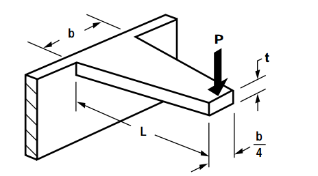
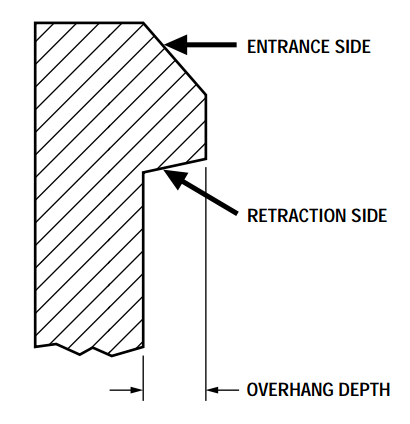
As you can see in the diagrams above, the cantilever snap joint is modeled by a fixed-free beam with a point-applied end load.
Refresher: Maximum Stress and Maximum Strain Basics for Cantilever Beam Design
The maximum stress and strain values are found at the root, or fixed end of the cantilever and can be easily approximated using classical beam bending theory. In simple terms, the basic equation for the maximum stress and maximum strain looks like this:
Maximum Stress for Cantilever Beams
Where: σmax = max stress
Ymax = distance from point to neutral axis
Mmax = max bending moment (force (P) * length of beam (L); @ free end of beam)
I = moment of inertia (based off beam geometry)
Maximum Strain for Cantilever Beams
Where: εmax = max strain
E = Young’s Modulus
Mmax = max bending moment @free beam end (force (P) * beam length (L))
Z = section modulus (I/dist to neutral axis)
As the exact forces are not yet known when designing a model, it’s most common to use deflection and strain rather than force and stress values to set your dimensions. In other words, your dimensions will be limited by maximum strain during deflection rather than the force required to assemble/disassemble (mating force).
To calculate maximum deflection, specifically, for plastic snap-fit joints, it must be noted that the ‘fixed end’ isn’t exactly fixed, because plastic components aren’t exactly rigid. To compensate for this, a factor, the deflection-magnification factor (known commonly as Q) was developed. Out of the finite element analysis (FEA) that sparked the origin of the deflection-magnification factor came a set of cantilever beam-style snap joint design equations for strain and mating force.
Strain Equation for Plastic Snap-Fit Design (Cantilever Snap Joint)
Where: εmax = max strain @ joint base
t = beam thickness
Y = deflection (snap)
L = beam length
Q = deflection-magnification factor
Mating Force for Plastic Snap Fit Design (Cantilever Snap Joint)
Where: W = push-on/pull-off force
P = perpendicular force
μ = coefficient of friction
α = lead/return angle
b = beam length
E = flexural modulus
L = beam length
While the rigid wall is the worst case for strain in the root, leave the deflection-magnification factor as 1 for a simple casing.
Also, note that the return angle affects the ease of joint separation. A return angle equal to the leading angle means the same force is used during assembly and disassembly. In contrast, a return angle of 90° can never be disassembled, except by using an external window to release the snap.
Implementing the Cantilever Calculations
Now that we know which calculation values are needed when designing a cantilever joint, let’s look at how to find those values.
There are two ways you can approach these calculations:
- Material first: You have chosen your material, found its allowable strain, and can design your dimensions to fit it.
- Dimensions first: Your primary dimensions are fixed and you can choose a material to fit.
Finding Acceptable Strain Limits
To find acceptable strain limits, use the yield stress and modulus of elasticity of the material with the following formula:
where ∈ = modulus of elasticity [MPa]
σ = stress [MPa]
E = strain [%]
So strain = stress/modulus of elasticity = change in length / initial length [%]
Pro Tip: 3D printed parts will have stress varying by axis, so for optimum strength, make sure the cantilever part of the joint is built along the X-Y plane and not traveling up the Z axis. If your cantilever can only be created in the Z axis, be aware that elongation at break is reduced by 50% and tensile strength by 20-30%. We recommend reducing the allowable stress/strain by 50% for Z-axis cantilevers. When uploading your design files, you can chat with a Fictiv team member if you have questions.
Here are the acceptable strain percentage values for common 3D printing materials:
| Material | Acceptable Strain |
| ABS-Like | 20-40% |
| VeroWhite | 10-25% |
| Transparent | 10-25% |
| ABS | 7% |
| PLA | 4-8% |
| Nylon | 4-15% |
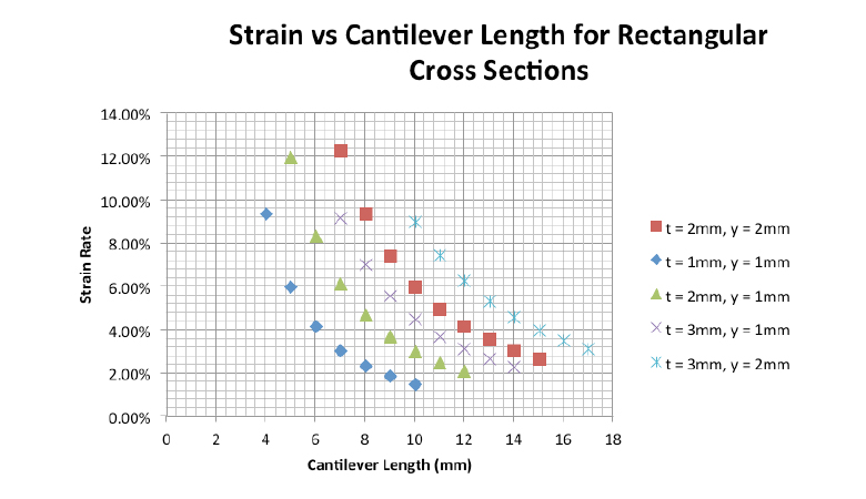
And here are some calculated strain rates for different wall thicknesses, deflections, and cantilever lengths to help you get started.
Changing Your Cantilever Cross-section
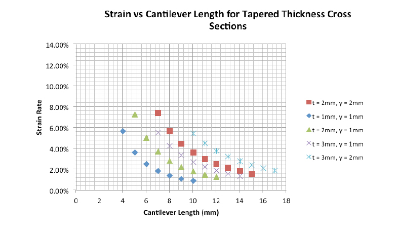
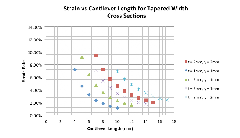
If you’ve calculated your dimensions and chosen your material, yet the acceptable strain rate is still too high, the best solution is to change the cantilever cross-section. The most common changes include tapering the width or thickness.
4 Common Problems and Solutions in Snap-Fit Design
Here are some solutions to other common challenges engineers face when designing snap-fit components.
1. Creep/Stress Relaxation
Thermoplastics are particularly susceptible to creep—the gradual, permanent deformation of the material under stress. Over time, this can compromise the connection between the male and female parts, or even render it useless.
Solution: Make sure your male and female parts are designed in such a way that while deflection may happen during assembly, the parts are not subjected to prolonged bending or tensile stress in normal, assembled use.
2. Stress Concentrators
Sharp corners concentrate stress at the root of the cantilever, causing it to shear off.
Solution: Make sure there are no sharp corners to act as stress concentrators, especially on the tensile side of the cantilever. Use radii or chamfers to reduce the chance of shearing.
3. Fatigue or Repetitive Loading Failure
Repeated assembling and disassembling of snap joints can cause failure at stresses much lower than the rated stress of your material. Fatigue failure typically happens at high loading frequencies (hundreds, if not thousands, of cycles).
Solution: If you anticipate high cycle frequencies for your component, careful selection of a fatigue-resistant material using S-N curves is essential.
4. Tolerances
The tolerances are wrong, and your parts won’t fit together.
Solution: Use this rule of thumb for gaps:
0.3 mm for close-fit snap joints
0.2 mm for tight fits
0.4 mm for slide fits and pivot joints
Tolerance Analysis Calculator
If you’re looking for a simple way to perform a tolerance analysis for your component, you can use our Tolerance Analysis Calculator. This easy-to-use Excel spreadsheet contains the calculators you’ll need for up to 10 different features.
DFM Considerations for Snap-Fits
Designing snap-fit features isn’t just about how they perform in assembly—it’s also about how easily and consistently they can be manufactured. Different production processes come with unique constraints that influence your design choices. Here are the key considerations for injection molding, CNC machining, and 3D printing.
Injection Molding Snaps
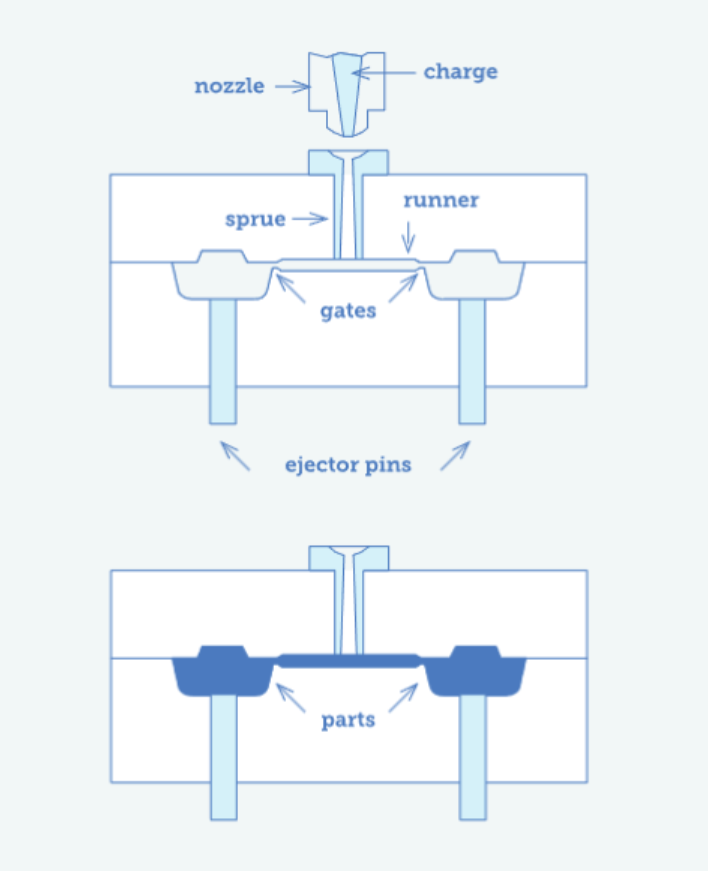
For injection-molded parts, remember that the mold dictates what’s possible.
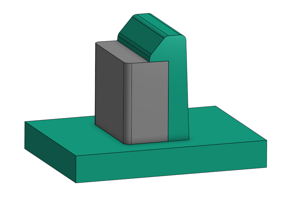
- Add draft: Include 1–2° of draft on both sides of snap arms and mating features to help the part release cleanly from the tool.
- Use rounds and fillets: Sharp corners at the base of a snap arm create stress concentrations and increase the risk of cracking. A radius about half the wall thickness at the root works well. Corner rounds also reduce stresses during assembly for a smoother fit.
- Keep wall thickness uniform: Avoid abrupt changes that can cause sink marks or warpage near the snap feature.
- Plan for flow: Gate near the base of the snap to encourage even filling and reduce weld lines, and be mindful of part orientation to minimize warping.
CNC Machining Snaps
Machining snap-fit prototypes can be a great way to validate your design before investing in tooling—but the process has its own limits. Careful design considerations must be made to avoid issues with thin walls.
- Mind tool access: Design with standard end-mill radii in mind (typically R0.8–R1.5 mm). Avoid deep, narrow slots or sharp internal corners that are difficult to machine.
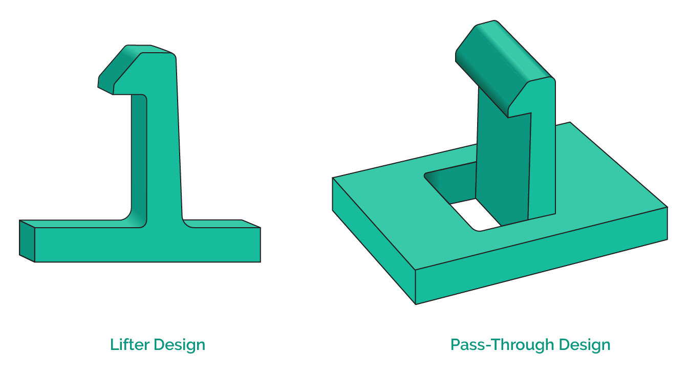
- Include reliefs and pass-throughs: Small relief cuts behind recesses prevent interference and simplify toolpathing. Pass-throughs allow simplified toolpath access to undercuts without additional setups.
- Avoid or support thin features: Use proper fixturing to avoid vibration or deflection when machining slender snap arms. Some snaps may be too thin to machine.
- Finish matters: A smooth surface reduces friction and makes assembly and disassembly feel more consistent.
3D Printing Snaps
Additive manufacturing offers flexibility for quick testing, but material properties and build orientation have a big impact on performance.
- Orient for strength: Print snap arms parallel to the build plane whenever possible. This aligns layer lines with the direction of deflection and prevents delamination.
- Choose the right material: Tough, flexible polymers like Nylon 12 or Onyx handle repeated deflection better than brittle resins.
- Account for tolerances: Leave a little extra clearance—typically 0.1–0.3 mm—depending on the printer and process.
Smooth it out: Post-processing like light sanding or vapor smoothing can improve fit and reduce stress risers.
Main Takeaways
Snap-fitting design is a complex and iterative process, but if you follow the simple engineering best practices covered in this article, you can improve the initial function of your snap-fit joints and decrease your prototyping life cycles.
Further Reading
We’ve only scratched the surface of snap-fits, so for a more in-depth analysis of snap-fit design and to dive deeper into the material properties, check out these guides.
Sourcing Simplified
If you’re tasked with sourcing and supplying mechanical parts, Fictiv is your operating system for custom manufacturing that makes part procurement faster, easier, and more efficient. In other words, Fictiv lets engineers, like you, engineer.
Learn more about our 3D printing and injection molding capabilities, then create your free Fictiv account to get started today.


