Time to read: 9 min
Ultrasonic welding is a joining method used across industries where parts are made from thermoplastics, metals, or other compatible materials. Its ability to quickly produce clean, reliable joints has made it indispensable in fields ranging from medical device manufacturing to automotive systems and consumer electronics. For teams focused on design for manufacturability (DFM), understanding ultrasonic welding is essential to ensure that products meet performance, cost, and regulatory compliance goals.
When you think of welding, you may picture hefty bars of steel and sparks flying across the visor of a welder. However, welding is a versatile assembly method that can also be applied to plastic parts. One of the most common and desirable ways to do this is ultrasonic welding.
This comprehensive guide to ultrasonic welding covers product design, covering process principles, equipment, geometry design guidelines, benefits, tradeoffs, and common applications. There’s also a link to get a free USW quote at the bottom.
What Is Ultrasonic Welding?
Ultrasonic welding is a solid-state joining process that uses high-frequency vibrations and pressure to bond parts. While most common in thermoplastics, it can also be applied to metals such as battery tabs and foils. Vibrations from a horn (sonotrode) press the parts against an anvil, generating localized heat that softens plastic or plastically deforms metals. With pressure maintained, the joint fuses as it cools.
Unlike vibration welding (100-300 Hz), ultrasonic welding operates at higher frequencies, resulting in faster welds and greater precision. Typical frequency ranges from 20-70 kHz, with 20 kHz for large parts or rigid materials (e.g., glass-filled polypropylene), 30–40 kHz (general thermoplastics), and 50–70 kHz for small, delicate parts like microelectronics or medical devices.
The Ultrasonic Welding Process: From Principle to Practice
Ultrasonic welding bonds thermoplastics using a simple sequence of vibrations + pressure → heat → fusion → solidification. The process includes the following stages:
- Setup & Alignment: Parts are positioned in a fixture that can be customized for precise fit and alignment. Locating features prevent lateral play, focusing energy at the intended joint.
- Horn Approach & Force Application: The horn descends and applies controlled force, pressing the parts against the anvil.
- Energy Conversion & Delivery: The generator and transducer convert electrical energy into high-frequency vibrations, transmitted through the horn. These vibrations create frictional heat, rapidly raising the local temperature.
- Melting & Material Flow: The thermoplastic softens and melts at the joint interface. If an energy director is used as recommended, it collapses, concentrating heat and promoting controlled flow of molten material.
- Hold & Solidification: After the programmed weld parameters (time, amplitude, or energy input) are met, vibrations stop while pressure is maintained. The material cools quickly, solidifying into a strong bond.
- Retraction & Inspection: The horn retracts, and the welded part is ejected or moved downstream for inspection and further processing.
Ultrasonic Welding Equipment Overview
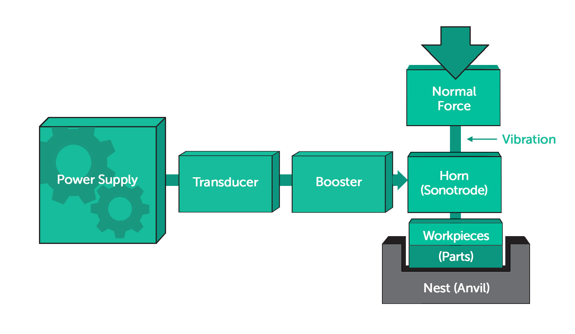
An ultrasonic welding system includes the following primary components:
- Generator: Converts standard electrical power into a high-frequency signal (typically 20–70 kHz).
- Converter (Transducer): Transforms the electrical signal into mechanical vibrations.
- Booster: Modifies the vibration amplitude and transmits it to the horn.
- Horn (Sonotrode): Delivers the vibrations directly to the parts being welded.
Together, these components form the ultrasonic stack, mounted in a precision press. The stack is most commonly arranged vertically, but certain automated or space-constrained systems use a horizontal orientation to accommodate part geometry or assembly layout. Proper tuning of the stack to its resonant frequency ensures efficient energy transfer and prevents overheating or inconsistent weld quality.
The nest (or anvil) supports and positions the lower part of the assembly. It provides a rigid, precisely machined surface that maintains alignment and transmits the clamping force evenly during welding. Well-designed nests reduce part vibration, improve weld consistency, and prevent cosmetic damage to finished surfaces.
As illustrated in Figure 1, the horn transmits vibrations to the workpiece, which is fixed against the anvil.
Benefits of Ultrasonic Welding
Ultrasonic welding offers several advantages over adhesives, solvents, or mechanical fasteners:
- Fast Cycle Times: Welds are completed in 0.5 to 2 seconds, making the process ideal for high-volume production.
- Cleaner: Unlike bonding with glues or chemicals–which require handling, curing, and often leave residue–ultrasonic welding produces joints without consumables, minimizing cleanup and improving workplace safety.
- Strong, Repeatable Joints: With proper joint geometry and tuned parameters, welds deliver consistent strength across thousands of cycles.
- Automation-friendly: Easily integrates into robotic or automated assembly lines, supporting lean manufacturing.
- Hermetic Sealing: Capable of forming airtight and watertight seals, critical in applications like medical devices and waterproof electronic housings.
Tradeoffs and Limitations of USW
While it offers valuable benefits, ultrasonic welding’s tradeoffs and limitations also need to be considered:
Material Compatibility
Works best with thermoplastics and certain metals. Amorphous plastics (e.g., ABS, polycarbonate) typically weld more easily, while semi-crystalline materials (e.g., nylon, polypropylene) require more energy input and careful joint design. Metals can also be ultrasonically welded, but as a solid-state process that relies on plastic deformation at the interface rather than melting. Thermoset polymers are not suitable for this application.
Process Tuning and Optimization
Achieving repeatable, high-quality ultrasonic welds often requires process tuning and validation. Small adjustments to parameters such as amplitude, weld time, hold pressure, and trigger force can significantly affect joint strength and appearance. Engineers typically use a trial-and-error or design-of-experiments (DOE) approach during prototype trials to identify optimal settings for a given material and geometry. Once parameters are established, production systems can maintain tight process control through sensors and closed-loop feedback, ensuring consistent weld performance over large volumes.
Part Size and Thickness
Best suited for small- to medium-sized components. Very thick or massive thermoplastic parts are challenging because it’s difficult to concentrate enough vibrational energy at the joint without it dissipating before effective softening occurs. This can lead to issues such as defects or bond failure.
Upfront Investment
Equipment and custom tooling involve higher capital costs than adhesives or simple fasteners, in part due to the precision electronics required. However, savings in cycle time, consumables, and labor often deliver payback in high-volume production.
Cosmetic Impact
Weld marks, flash, or joint lines may be visible and may require design adjustments or post-process treatments in applications with strict aesthetic demands.
Product Design Considerations for Ultrasonic Welding
Successful ultrasonic welds rely not only on the right equipment but also on careful part design. The following factors are crucial to achieving strong, consistent, and repeatable welds:
Energy Directors
Energy directors are triangular or trapezoidal ridges molded into one mating part to focus ultrasonic energy at the weld line. The sharp edge softens under vibration and collapses into the joint, creating a controlled melt. Amorphous plastics allow consistent collapse of the energy director, while semi-crystalline materials may require larger or double energy directors to ensure complete melt. For these materials, incorporating a small melt trap or secondary ridge can help capture excess flash and improve joint cosmetics.
Early weld trials are often used to fine-tune the height and angle of the director for each resin formulation. Guidelines suggest a height of 0.2–0.5 mm (≈ 0.008–0.020 in) and an apex angle of 45°–60°, with the lower range used for thin parts or high-frequency welding, and the higher end for thicker parts or lower frequencies. Designing for predictable collapse ensures the feature deforms consistently, maintaining weld strength and avoiding flashing or incomplete bonding.
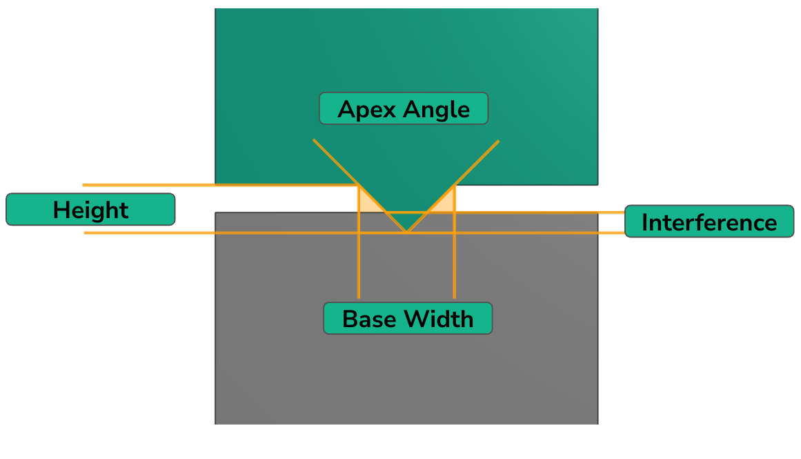
Figure 2 Energy director profile with interference for melt depth
Joint Geometries
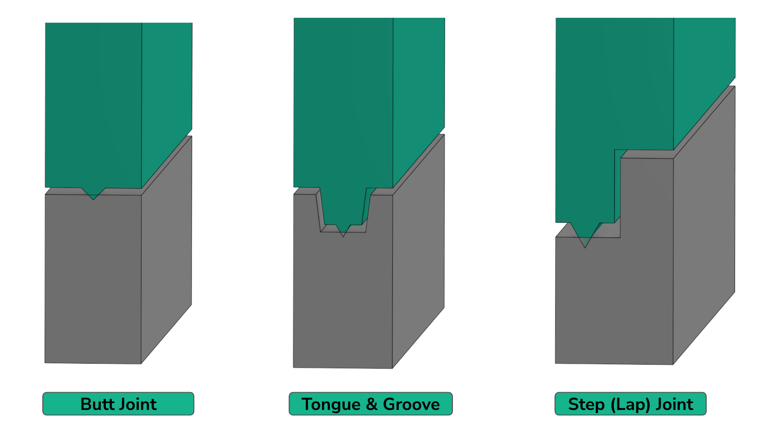
The geometry of the joint plays a major role in alignment, aesthetics, and weld performance. While some joint designs are used across many welding processes, in ultrasonic welding, certain shapes are preferred and others are avoided. Commonly used geometries include:
- Butt Joint: Two flat surfaces pressed together. Simple and inexpensive, but with lower peel strength; best for sealed joints under light loads.
- Shear Joint: One wall overlaps another, so vertical movement during welding creates a shear force at the interface. Provides high strength, especially for semi-crystalline plastics.
- Step Joint: One part includes a step feature into which the other part fits, improving self-alignment and producing cleaner external cosmetics.
- Tongue-and-groove Joint: A protruding tongue fits into a groove on the mating part, offering mechanical interlock, improved alignment, and reduced flash.
Avoid large flat interfaces with no features to concentrate energy, as they make melting difficult to control. A good joint should provide precise alignment between parts, concentrating energy (via energy directors or overlapping walls), and control over flash and aesthetics.
Material Selection
Choose plastics known to respond well to ultrasonic welding. Amorphous plastics (such as ABS or polycarbonate) are typically easier to weld, while semi-crystalline plastics (such as nylon or polypropylene) can be more challenging. Additives like glass or carbon fibers affect how the material absorbs ultrasonic energy and how the molten material flows at the joint. These changes can influence weld strength, cosmetic finish, and process stability.
Tolerances & Alignment
Tight dimensional control of the parts to be joined is critical to weld quality and consistency. Even small variations can lead to weak or incomplete bonds. Use locating bosses, pins, or grooves in the design to ensure a consistent fit and contact. Specify mold tolerances that keep the weld seam within the intended collapse height range so the joint fuses properly without excessive flash or incomplete bonding.
Applications of Ultrasonic Welding in Product Design
Ultrasonic welding is used across a wide range of industries because of its ability to create strong, clean, and reliable joints without adhesives or additional fasteners
- Medical Devices: Syringes, catheters, and diagnostic devices, such as housings for test kits and analyzers, require hermetic sealing to maintain sterility and prevent contamination. Consistent welds help ensure safety and compliance with strict medical standards.
- Electronics: Smartphone housings, sensors, and connectors support miniaturization while avoiding thermal damage to sensitive components.
- Automotive: Interior panels, fluid reservoirs, sensors, and filters where durability and vibration resistance are critical.
- Consumer Goods and Packaging: Battery housings, toys, and blister packaging enable fast production cycles, secure seals, and good cosmetics.
Alternative Assembly Methods to Ultrasonic Welding
While ultrasonic welding is highly effective, other joining methods may be considered depending on design requirements. Adhesives, for example, offer flexibility and can join dissimilar materials, a capability that ultrasonic welding generally lacks. However, they require curing time, add consumable costs, and often result in slower production cycles.
Mechanical fasteners provide strong and removable connections but increase part count, add weight, and require secondary operations such as drilling or tapping. Solvent bonding is a simple and inexpensive method that chemically fuses plastic parts. Despite its low cost, it raises safety and environmental concerns and offers limited precision.
Table 1 highlights the key differences across performance, cost, and design requirements.
| Factor | Ultrasonic Welding | Adhesives | Fasteners | Solvent Bonding |
| Cycle time | Seconds | Minutes to hours (depends on curing) | Seconds to minutes (manual or automated insertion) | Minutes (application + evaporation/ curing) |
| Consumables | None | Adhesive material required | Screws, rivets, clips, etc. | Solvent required |
| Cleanliness | Minimal residue, minimal fumes (localized heating) | Potential outgassing, messy application | Plastic or metal shavings from holes, possible corrosion | Solvent vapors require ventilation |
| Strength | Strong, permanent bonds | Strong, but material- and environment- dependent | Strong, can be designed for rework | Strong but may weaken over time (stress cracking, aging) |
| Hermetic sealing | Excellent (airtight, watertight) | Variable, depends on the adhesive | Poor unless gaskets/seals are added | Good sealing if the joint design is tight |
| Design flexibility | Requires thermoplastics and joint geometry designed for energy transfer | Can join dissimilar materials, but joint design affects stress | Can join dissimilar materials, but adds holes/hardware | Limited to compatible plastics, joint geometry affects solvent flow |
| Aesthetics | Minimal marks (some flash possible) | Invisible joints possible | Visible hardware | Usually clean, but risk of discoloration |
| Disassembly | Not possible (permanent) | Permanent, sometimes reversible with solvents/heat | Easy (threaded) or permanent (rivets) | Not possible (permanent) |
| Cost (per unit) | Higher initial equipment cost, very low per-part cost | Low equipment cost, moderate per-part cost | Low equipment cost, ongoing parts + labor cost | Very low equipment cost, low per-part cost |
Table 1: Comparison of ultrasonic welding with other joining methods
Ultrasonic Welding Best Practices
- Use energy directors to localize heat and control melt flow.
- Maintain tight part tolerances and good surface contact.
- Choose amorphous plastics for easier welding.
- Validate weld parameters early through prototype trials.
Key Process Parameters For Ultrasonic Welding
- Amplitude: Determines vibration magnitude (typically 10–100 μm).
- Weld Time / Energy: Controls the duration or total energy input.
- Hold Pressure: Maintains clamping during solidification.
- Trigger Force: Ensures consistent contact before vibration begins.
Design for Success With Fictiv’s Ultrasonic Welding Services
Ultrasonic welding offers engineers a powerful tool for assembling thermoplastic components quickly and reliably. The key to success lies in designing with welding in mind, choosing the right materials, incorporating energy directors and correct joint geometries, and effective communication with the supplier you choose.
Ready to explore ultrasonic welding for your next product? Fictiv offers design support, prototyping, and production solutions that ensure your assemblies meet the highest standards for performance and manufacturability.
Reach out to our team or upload your design for a free quote to get started.


