



Engineering Thermoplastic

UHMW

CNC UHMW Components — Ultra Tough, Abrasion-Resistant Plastic Parts
UHMW

At a glance

Processes

CNC Mill
CNC Lathe

Lead Time

As fast as 3 days

Colors

White, black

Tolerance

With drawing: as low as +/- 0.005 mm
No drawing: ISO 2768 medium

Price

$

Applications

Machine guards, liners in chutes and hoppers

About the Material

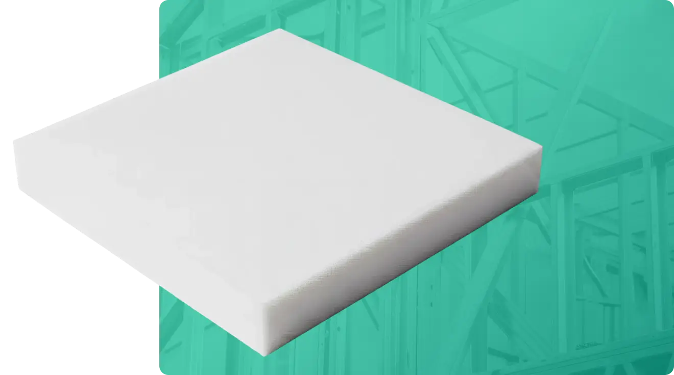
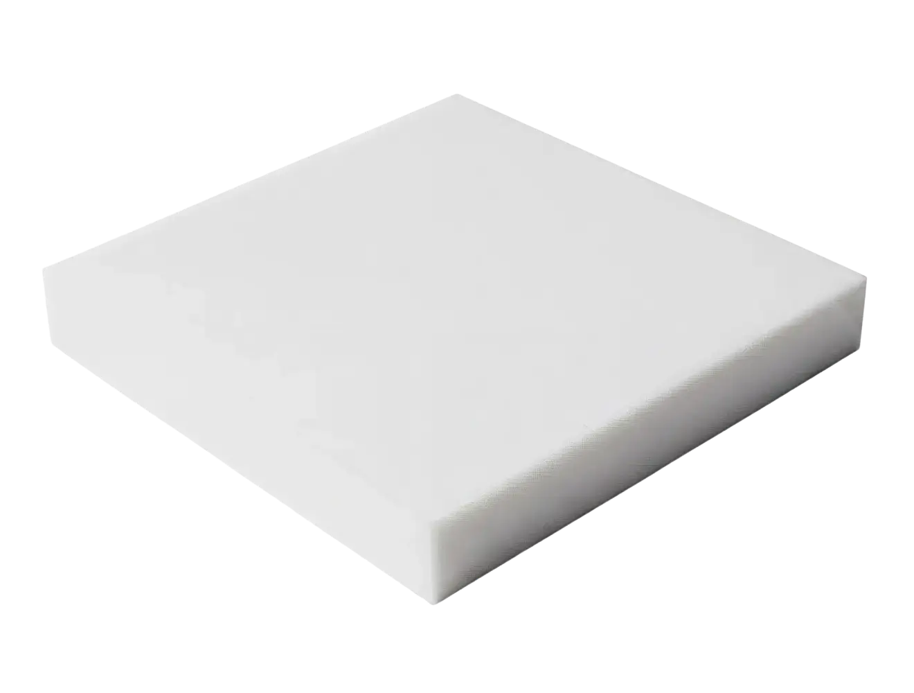
Ultra-High-Molecular-Weight Polyethylene (or UHMW) is a hard plastic with a slippery surface, which resists abrasion and wear. Additionally, it offers high impact strength and is the optimal material for chute/hopper liners and machine guards.

Lubricity

Extreme Toughness Icon

Endurance

Extreme Toughness Icon

Material Properties

UHMW

Yield Strength (tensile)

5,000 psi

Elongation at Break

200%

Hardness

Durometer 70D

Density

0.034 lbs / cu. in.

Maximum Temp

180° F

McMaster Part Number

8752K831

Material Finish

UHMW comes in an opaque black or white color and can be machined to a range of surface finishes. It also has a slippery texture, which is ideal for machine guards and liners.

Design Recommendations

Min Wall Thickness

0.5 mm

Min End Mill Size

0.8 mm (0.03 in)

Min Drill Size

0.5 mm (0.02 in)

Max Part Size

1200 x 500 x 152 mm [x,y,z] (mill)
152 x 394 mm [d,h] (lathe)

Undercuts

Square profile, full radius, dovetail profiles

Radii : Depth

Depth must not exceed 12x drill bit diameter.
For end mills, depth must not exceed 10x tool diameter.
Cost Saving Tip

Cost Saving Tip

To reduce costs, limit the number of part setups, the number of inspection dimensions or tight tolerances, and deep pockets with small radii.

You Might also be Interested in

Header image: ‘Manufacturing Process Selection: 5-step framework’ with five connected steps: Step 1 Volume and timeline, Step 2 Geometry constraints, Step 3 Material requirements, Step 4 Tolerance and surface finish, Step 5 Cost model.

Manufacturing Process Selection: A Guide to Choosing the Right Production Methods

The manufacturing process you select impacts part cost, lead time, achievable tolerances, material options, and how easily you can iterate…

Learn more >
Left-aligned article header: 'The Impact of AI in Mechanical Engineering' with subtitle on a dark background; brand 'fictiv' logo visible. Right side shows a teal, high-tech schematic with an AI core and connected nodes.

The Impact of AI in Mechanical Engineering

Artificial Intelligence is no longer on the horizon for mechanical engineers—it’s already on our desktops, inside our CAD tools, and…

Learn more >