Time to read: 6 min
A compliant mechanism is a mechanical system that uses flexible components such as springs, cables, and linkages to absorb energy, provide compliance, and reduce the overall stiffness of a system. Compliant mechanism designs use flexible members (often 3d printed) to achieve a prescribed range of motion and/or force.
There are also secondary benefits to compliant mechanisms that are frequently overlooked. Just like a spring or another flexible connection, a compliant mechanism can be used to absorb a shock while performing a desired function or maintaining a desired output.
As designers and engineers, technical terms can prevent us from working effectively with other departments. For example, “a compliant mechanism is best for our application” sounds good, right? But saying “a compliant mechanism will reduce cost and save time” will get you company-wide buy-in. To make such a bold claim with confidence, however, you need to thoroughly understand the underlying principles of compliant mechanisms.
Thankfully, there are examples of compliant mechanisms everywhere and using beam theory with linear assumptions (F=kx) is usually a suitable method for designing and understanding them. Read on to learn about common utilizations, applications, and design of compliant mechanisms.
Compliant Mechanisms in Daily Life
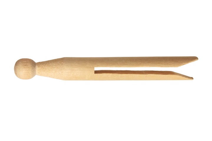
Compliant mechanisms are useful because they use flexible members to reduce the number of parts and manufacturing steps required to produce a functioning assembly or perform a specific function. Here’s an example of a compliant mechanism vs traditional design you’re likely familiar with: the clothespin. The image on the left shows the traditional mechanism clothespin, while the image on the right shows the compliant mechanism clothespin.


LEFT: 3 Part Traditional method clothespin RIGHT: Compliant Mechanism Clothespin (Dolly peg)
Let’s break down the traditional versus the compliant mechanism to see how beneficial designing a compliant mechanism actually is. Check out the table below for specifics, but the results speak for themselves — the compliant mechanism design is simpler and functions just as well.
Traditional Mechanism Clothespin vs Compliant Mechanism Clothespin
| Traditional Mechanism Clothespin | Compliant Mechanism Clothespin | |
| Motion Requirement | Limited range (Diameter of a clothesline + thickness of clothing) | Limited range (Diameter of a clothesline + thickness of clothing) |
| Force Requirement and type | Keep clothes on the line, clamping | Keep clothes on the line, clamping |
| Total Parts | 3 | 1 |
| Number of Materials | 2 | 1 |
| Number of Manufacturing Methods | 2 | 1 |
| Number of Assembly Steps | 1 or 2 | 0 |
Looking at the table above, the cost and time benefits are clear. Fewer parts, fewer processes, fewer steps = reduction in COGS (Cost of Goods Sold). The compliant mechanism design wins in this battle!
Application of a Compliant Mechanism
It may seem like a compliant mechanism design is always the way to go because generally, simple is better, but you can’t always simplify things. There are specific applications for which a compliant mechanism can be utilized and for the rest, stick with a traditional design.
Generally speaking, compliant mechanisms are best for low-risk and prototype applications. So, if you’re doing a proof-of-concept, making a test apparatus or tool, or making something that isn’t going to be moved millions of times (fatigue failure over repetitive loading cycles is a concern), then a compliant mechanism is the way to go. If, however, you need a long service life (millions of cycles), or if you’re working on a high-risk application (life-saving device), a compliant mechanism is probably not the best choice.
To understand potential use cases for complaint mechanisms, we first need to understand the benefits and limitations of compliant mechanisms. Here’s an overview of their advantages and disadvantages:
Advantages of Compliant Mechanisms:
- Simplicity
- Fewer Parts
- Fewer production methods needed
- Fewer assembly steps
- Reduced cost per unit (typically at the expense of service life)
- Faster to produce and faster to test
- Absorbs energy and shock loads (like a spring)
Disadvantages of compliant mechanisms
- Non-linear equations (this should ONLY be applicable for final production)
- Fatigue (limited loading cycles if under-designed)
- Limited motion (can break)
- Provides a non-rigid connection
How do I Design a Compliant Mechanism?
Usually compliant mechanisms replace added springs, or eliminate parts in a traditional mechanism. Designing a compliant mechanism can be easy if you apply the right methods and techniques — using good engineering judgment is key to getting it right on your first try.
You can follow these steps to form a foundation for designing a compliant mechanism:
- Use simplified assumptions of linearity (think beam theory); depending on your application, break the motion you want to replace down to the simplest formulas that govern the motion itself.
- Constrain your problem (force requirements, range of motion, weight); make assumptions where needed.
- Turn everything into a simple beam problem; for the most part, beam equations can be utilized to measure how the modulus of elasticity and applied loading conditions impact the resulting stress distribution and deflection of a member.
- Choose your manufacturing method and apply best practices for DFM (i.e., if using FDM 3D printing, print orientation matters just like the grain in a wooden board)
- Use manufacturer supplied datasheets for the materials to obtain material properties (i.e. young’s modulus)
- Use a factor of safety for failure criterion that is between 5x and 10x of yield strength or range of travel (strain) to solve for the required geometry of your compliant mechanism.
Example of a Compliant Mechanism Analysis
The above list takes you through prototyping and proof-of-concept testing where it’s safe to use linear assumptions (imprecise) and beam analysis (artificially flexible or rigid compared to reality) — as long as you have an adequately high factor of safety to cover the inaccuracy of your assumptions. If you’re pushing a design to production, then you need to run simulations to optimize the design and further reduce failures.
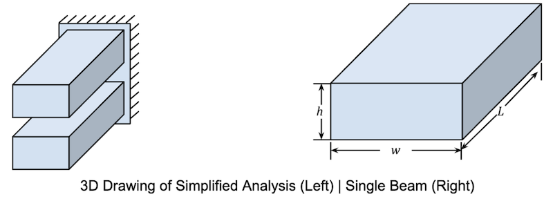
In our clothespin example, the most direct approach is to analyze the “Compliant Mechanism Clothespin” as two, linear-elastic, homogeneous, straight, rectangular, cantilever beams (fixed-free). This is only a correct assumption if the support is thick enough:

Let’s constrain the problem by saying we have a known displacement, x, and we don’t want our parts to break, so the stress must be below yield strength.

Using Hooke’s Law (F=kx) and Beam Theory, we need Young’s modulus for the material and the beam’s parameters. Armed with that information, we can input the Moment of Inertia and solve for displacement, or force at the end of one beam. For this example, x, is given and we are solving for F.
![]() (Hooke’s Law)
(Hooke’s Law) ![]() (Beam Theory, effective spring constant of fixed-free cantilever beam)
(Beam Theory, effective spring constant of fixed-free cantilever beam)![]() (Moment of inertia)
(Moment of inertia)![]()
![]() (Combining, 1, 2, and 3)
(Combining, 1, 2, and 3)
F can be limited by “minimum holding force”, “maximum crushing force”, or more frequently “material failure”. For this example, we will limit ourselves to material failure. Another parameter that is not commonly given is “Flexural Strength” (stress at failure in bending), and this is where engineering judgment is required. We assume the flexural strength is equal to or slightly larger than the failure stress in tension, and it’s because of this assumption that we pad our results with a high factor of safety. Continuing to solve for geometries that are within the yield strength (𝝈yield) of the material, subject to the known displacement “x”.
![]() (Yield Stress equation for a cantilever beam)
(Yield Stress equation for a cantilever beam)![]() (Combining 4 and 5)
(Combining 4 and 5)
An effective design that will not fail can be achieved by tweaking h and L in equation (6). Adding in a factor of safety (recommended 5x-10x) will ensure a successful first print.
Unless you’re working on a high-risk application (life-saving mechanism) or one that requires a long service life (millions of cycles), the simplified assumptions in this article will work — F=kx isn’t going anywhere, anytime soon. The above methodology is proven to help you save on COGS (cost of goods sold) and development. Compliant mechanisms and good engineering design reduce raw material costs, reduce assembly steps, and reduce time to prototype or production.
For more nuanced applications including aerodynamics and vibrational loading, these linear assumptions will take you into the right area of design. Thorough simulations using non-linear assumptions and real-life testing are the only ways to say whether or not the design will work as a solution for more complex problems.
Fictiv Delivers Complex Parts at Ridiculous Speeds
Whether you’re building a compliant mechanism or something more complex, Fictiv has you covered. Our manufacturing network has experts in injection molding, CNC machining, 3D printing, and urethane casting who produce custom precision mechanical parts from a variety of materials. And the Fictiv platform simplifies custom part sourcing with intelligent, streamlined, automated workflows.
Fictiv is your operating system for custom manufacturing that makes procuring even the most complex parts faster, easier, and more efficient. Create an account and upload your design today to see what our instant quote process, design for manufacturability feedback, and intelligent platform can do for you.


