Time to read: 8 min
Product engineering teams rely heavily on simulation tools to predict how a product will behave before it’s ever built. These tools make it possible to quickly explore design ideas and catch potential issues before they arise. Even the most advanced simulation, though, cannot perfectly predict real-world behavior—which is why simulation validation and structured prototyping are so important.
How Does Simulation Compare to Reality in Hardware Development?
Simulation vs. reality in hardware development refers to the process of validating digital models—such as finite element analysis (FEA) or computational fluid dynamics (CFD)—with physical prototypes and real-world testing. While simulation helps engineers predict performance early, it relies on assumptions about materials, geometry, and boundary conditions. To ensure a design performs as intended, engineering teams must use structured prototyping, validation phases like EVT, DVT, and PVT, and iterative testing to close the gap between simulated results and real-world behavior.


Move faster with a partner built for regulated programs.
Upload your part and get a compliant quote—from a team with the systems, workflows, and experience to keep your program on schedule.
See what your part would costThe Simulation–Reality Gap
There’s no question that simulation is useful for accelerating product development. Engineers can evaluate thermal behavior, stress distribution, airflow, structural performance, and more before a prototype is made. Design iterations can be tested digitally to screen out non-viable design choices, getting to the best possible design for prototyping in a matter of hours rather than weeks—without the headaches and expense of testing each prototype.
However, simulations are not always 100% accurate. There will always be a difference between simulation and reality because simulations are mathematical representations of the real world. These mathematical models depend on a list of assumptions. They assume specific material properties, ideal boundary conditions, and perfect part geometry, all of which are variables in reality but may be fixed in a model. This is why prototyping and real-world testing remain critical.

Why Simulation and Reality Diverge in Hardware Development
There are several reasons why simulation results can differ from real-world performance. Most of these differences stem from the necessary assumptions and simplifications made during modeling. Some of the main causes of the gap between reality and simulation include:
- Material property assumptions
- Boundary condition simplifications (the applied rules or environmental interactions set by the designer/engineer that determine how the simulation should interact in real-world conditions)
- Idealized geometry vs. manufacturable geometry
- Tolerance stack-up
- Assembly variation
- Environmental conditions (e.g., temperature fluctuations, dynamic loading, and friction behavior)
For long-life components, wear and tear can also affect real-world performance over time.
Common Causes of Product Simulation Error
| Assumption | What Simulation Assumes | What Happens in Reality |
| Material properties | Nominal data sheet values | Material properties can vary as much as 15% depending on supplier lot and processing method |
| Geometry | Perfect CAD model | Manufacturing deviation (tolerances) |
| Boundary conditions | Fixed constraints | Dynamic loads and movement |
| Friction and contact | Simplified models | Nonlinear behavior and wear |
| Assembly | Ideal alignment | Real-world misalignment and tolerance stack-up |
These differences explain why simulation results must always be validated through physical testing.
Verification vs. Validation vs. Correlation
Engineers use three key concepts to evaluate designs and simulations: verification, validation, and correlation. While they sound similar, they represent distinct steps in ensuring a product performs as intended.
Verification asks: Was the design implemented correctly? It focuses on confirming that the product meets engineering specifications, drawings, and requirements.
Validation asks: Does the product work in the real world? It evaluates whether the design performs as intended under actual operating conditions, including environmental and use-case factors.
Correlation asks: How closely do simulation results match physical test data? After prototypes are tested, engineers compare measured results with simulation predictions to identify gaps and improve model accuracy.
Correlation methods may include:
- Curve fitting vs. physics-based model updates
- Using test data to calibrate FEA models
- Measurement tools such as strain gauges, thermal imaging, and digital twins
Sometimes, engineers calculate a correlation factor to quantify how closely simulation results align with experimental data, providing a measurable level of confidence in the model.
When updating simulation models, engineers must avoid simply tuning parameters to match test results. The goal is to improve the model so it reflects real physical behavior—not to artificially “fit” the data. When done correctly, correlation strengthens simulation reliability and leads to better design decisions in future iterations.

Engineering Validation Phases: EVT, DVT, and PVT
Most hardware development programs structure validation testing into three phases: Engineering Validation Testing (EVT), Design Validation Testing (DVT), and Production Validation Testing (PVT).
Different Validation Priorities at Each Stage
| Phase | Primary Goal | Simulation Role | Physical Focus |
| EVT | Functional proof | Model correlation | Core performance testing |
| DVT | Reliability validation | Sensitivity analysis | Environmental and stress testing |
| PVT | Production readiness | Stability confirmation | Production yield and repeatability |
During EVT, the primary goal is to confirm that the design works at a fundamental level. Engineers build early functional prototypes and compare test results to simulation predictions, with a heavy focus on test-to-analysis correlation to ensure that models align with real-world behavior.
Once the core design is validated, teams move to DVT. In this stage, the focus shifts toward reliability, environmental testing, and tolerance sensitivity. Products may be tested under temperature cycling, vibration, or long-term stress conditions to confirm durability and regulatory compliance.
Finally, PVT validates the manufacturing process itself. By this stage, the design should already be stable. The goal is to confirm that production methods can consistently produce parts within specification and achieve an acceptable yield.
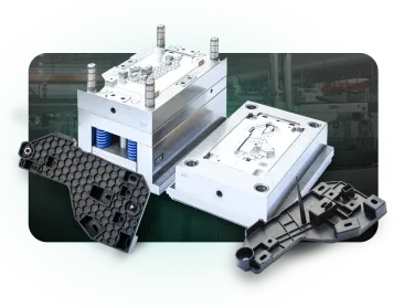
The Low-Volume Injection Molding Guide

Iteration Strategy: How to Move Fast Without Mistakes
Iteration is a normal part of hardware development. Designs rarely work perfectly on the first attempt, so engineers refine and improve them through multiple prototypes and testing cycles. Without structure, however, iteration can quickly lead to delays and confusion.
Successful teams manage iteration carefully. Simulation and prototyping often run in parallel, allowing engineers to test ideas digitally while physical testing continues. This helps teams learn faster and identify improvements earlier in the development process.
It’s also important to control design changes. Each iteration should clearly document what changed, why the change was made, and the expected impact. Without this discipline, it becomes difficult to isolate which changes improved performance and which created new problems.
Engineers also need to know when to stop iterating. Once the design meets performance requirements and manufacturing constraints, further optimization tends to offer diminishing returns while adding unnecessary time and cost.
Manufacturing Reality: The Hidden Variable
One factor that simulations often struggle to capture is manufacturing reality. In simulation, parts are often modeled as perfectly shaped components with ideal material properties and precise dimensions. In practice, however, manufacturing processes introduce variations and constraints that can affect how a product performs. These differences are frequently the culprit when simulated and real-world results fail to match exactly.
Common manufacturing factors that influence hardware performance are:
- Tolerances: Small dimensional variations can change load paths and stress distribution.
- Surface Finish: Rougher surfaces can affect friction, wear, and fatigue life.
- Assembly: Alignment, fastener torque, and assembly order can influence how forces move through a system.
This is why design for manufacturability (DFM) is so important early in the development process. Manufacturing feedback helps engineers understand how parts will actually be produced and assembled, allowing them to refine both the design and simulation models.

When Can You Trust Simulation vs. When You Need Physical Prototypes
Simulation is highly effective for screening design concepts, optimizing geometry, and reducing early-stage risk. However, it should not be treated as final proof of performance. As a general rule, simulation is most reliable when material behavior is well characterized, loading conditions are predictable, and manufacturing variation has minimal impact on performance.
Simulation is most accurate and reliable when:
- The underlying physics are well understood, such as in linear static FEA problems
- Material behavior is predictable and consistent with isotropic and well-characterized properties
- Boundary conditions are clearly defined with minimal uncertainty or real-world variability
- Mesh quality is well controlled, with sufficient resolution in areas of high stress or complexity
Physical prototyping becomes essential when:
- Tight tolerances or assembly interactions influence performance
- Materials exhibit nonlinear, temperature-dependent, or fatigue behavior
- Environmental conditions (humidity, vibration, thermal cycling) are significant
- Safety, regulatory, or reliability requirements must be validated
In practice, the most effective teams use simulation to reduce design space early, then rely on prototyping and validation testing to confirm performance before production.
Common Mistakes in Simulation-to-Reality Transitions
There are a number of common mistakes designers can make when transitioning from simulations to manufacturing:
- Treating the simulation as proof: Failing to validate designs in the real world before committing to a final product can lead to the product not performing as intended, as discrepancies between simulations and the real world add up.
- Testing everything at once: When validating simulations, it helps to isolate specific parameters or properties to test. This makes it easier to find the root cause of any deviations from the simulated data.
- Skipping correlation: Designers often fall into the trap of relying solely on pass/fail testing. While this is useful for meeting minimum requirements, correlation testing can give you a much richer understanding of how accurate your simulations are, which can go a long way to ensuring that the final product performs as intended.
- Ignoring manufacturing constraints: Different manufacturing methods have different constraints, such as geometric or material limitations. Simulation software doesn’t typically enforce these constraints by default, so designers need to account for them to ensure they don’t end up with a product that’s impossible to manufacture.
![Fictiv for prototyping validation.]()
Simulation Is a Tool—Validation Is the Proof
Simulation tools help engineers explore designs faster and make better decisions early in development. But because simulations rely on assumptions, real-world performance testing is essential.
Successful hardware development combines simulation, prototyping, and structured validation. Through careful testing, model correlation, and controlled design iteration, teams can close the gap between digital predictions and physical reality.
Fictiv helps hardware teams move from digital models to validated prototypes faster with rapid manufacturing, DFM insights, and scalable production support.
FAQ: Simulation vs. Real-World Testing in Hardware Development
What is the difference between simulation and real-world testing in engineering?
Simulation uses mathematical models to predict how a design will perform, while real-world testing validates those predictions using physical prototypes. Simulation helps engineers explore design options quickly, but physical testing is required to confirm performance under real conditions, including manufacturing variation and environmental factors.
Why is simulation not enough in product development?
Simulation relies on assumptions about materials, geometry, and boundary conditions, which may not fully reflect real-world variability. Factors like tolerance stack-up, assembly variation, and environmental conditions can significantly impact performance. Physical testing ensures the product works as intended outside of idealized models.
What are EVT, DVT, and PVT in hardware development?
• EVT (Engineering Validation Testing): Confirms core functionality and initial performance
• DVT (Design Validation Testing): Tests reliability, durability, and environmental performance
• PVT (Production Validation Testing): Validates manufacturing processes, yield, and consistency
These stages help teams systematically reduce risk before full production.
What causes simulation errors in engineering models?
Common causes include inaccurate material properties, simplified boundary conditions, idealized geometry that doesn’t reflect manufacturing constraints, and real-world factors like friction, wear, and environmental variation. These limitations are why simulation results must be validated through testing.
How do engineers validate simulations?
Engineers validate simulations by building prototypes and comparing test data to model predictions. This process, known as correlation, helps identify gaps between simulation and reality and allows engineers to refine models for improved accuracy in future design iterations.
What is the fastest manufacturing process?
3D printing is typically the fastest to start since it requires no tooling, while CNC machining offers fast turnaround for functional parts. Injection molding and die casting have longer lead times due to tooling but are faster for large-scale production.

Injection Molding Design Guide