







Time to read: 8 min
What Is Design for Testability (DFT)?
Design for Testability is the practice of deliberately engineering a product so that its functions, performance, and integrity can be efficiently verified at every stage: prototype validation, end-of-line production testing, incoming inspection, field service, and depot-level repair. When testability is baked in from the start, you catch failures earlier, reduce test fixture complexity, cut test cycle times, and lower the overall cost of quality.
A product that works in the engineering lab but fails in the field, or ships with a defect that wasn’t caught because no one could reach the test point, is a failure of design, not just manufacturing. That’s the problem Design for Testability (DFT) is built to solve.
DFT sits within the Design for Excellence (DFX) family of engineering disciplines. Just as DFM (Design for Manufacturability) asks “can this be built efficiently?” DFT asks “can this be verified efficiently?” Both questions need to be answered before a design is finalized.

Design for Test vs. Design for Testability: Is There a Difference?
The terms are often used interchangeably, but there’s a meaningful distinction worth understanding.
Design for Test refers to adding specific hardware features to a product—test points, connectors, breaks in a circuit, alignment datums—that enable a test system to stimulate inputs and measure outputs. It’s often associated with the electronics world (boundary scan, JTAG, built-in self-test) but applies equally to mechanical assemblies.
Design for Testability is the broader discipline. It encompasses not just which hardware features you add, but how you structure the architecture, tolerances, documentation, and assembly sequence so that the product is inherently observable, controllable, and isolatable. A product with good testability may require fewer special test features because it was designed from the ground up with testing in mind.
For physical mechanical products, both matter. Your architecture choices—how you modularize subsystems, where you put interfaces, how you define tolerances—determine whether testing is fast and accurate or slow and ambiguous.
Why Testability Matters for Mechanical Products
Most DFT literature focuses on electronics and semiconductors, where the stakes of poor testability are well-documented, but mechanical products have an equally compelling case. Functional testing at end-of-line for assembled products like pumps, actuators, HVAC components, medical devices, and robotic arms represents as much as 10–30% of total manufacturing cost, and poor testability increases those costs.
A defect that slips through production testing costs much more to fix in the field. Products that are hard to diagnose in the field require more technician time, more speculative parts replacements, and higher service spares inventory. Compressing mean time to repair (MTTR) is one of the most cost-effective outcomes of good DFT. In aerospace, medical, and automotive safety applications, testability is often a regulatory requirement, not just a cost lever.
As mechanical products incorporate more embedded electronics, sensors, and software, their testability challenges multiply. A purely mechanical approach to DFT is no longer sufficient—today’s mechanical engineers need to think across domains.
Core Principles of Design for Testability
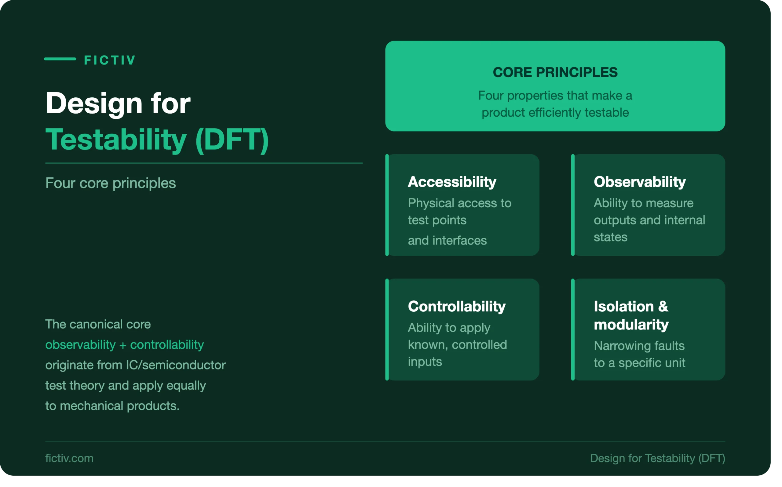
- Accessibility
The most fundamental testability problem in mechanical products is physical access. If a test probe, sensor, or torque transducer can’t reach the feature being measured, you can’t test it directly. In practice, this means providing clearance around critical interfaces for tooling and instrumentation, including dedicated test ports (pressure taps, electrical connectors, optical access windows) in early design, and designing assemblies so functional tests can be performed at intermediate stages rather than only after final integration.
Test points are the physical realization of accessibility: the locations where instrumentation interfaces with the product. An example is CMM inspection: reference datums must be positioned with sufficient surrounding clearance for a touch probe to reach them without crashing into adjacent features—a constraint that belongs in the tolerance model from the start, not discovered at inspection. A useful design review question: “How would I instrument this to measure its performance?” If the answer requires disassembly of adjacent systems, the design may need to change.
- Observability
Observability is the ability to infer a system’s state from its outputs. Good testability requires that the outputs you care about—force, pressure, flow, position, temperature, torque, vibration—are measurable without excessive setup or disassembly. Design choices that improve observability include integral measurement interfaces (pressure taps, thermocouple bosses, encoder targets, strain gauge bonding surfaces) and instrumentation ports between functional stages in fluid systems.
In practice this means designing for the specific shop-floor tools that will be used: for fluid manifolds, machining dedicated flat sealing faces so an automated pneumatic decay tester can achieve a repeatable volumetric seal; for rotating assemblies, milling flat target pads at accessible locations so a laser vibrometer can detect early bearing wear without disassembly. Where direct measurement isn’t feasible, the design should produce observable side effects—vibration signatures, torque profiles, flow curves—that correlate reliably with the functional parameter of interest.
- Controllability
A test is only meaningful if you can apply a known, controlled input and measure the response. Controllability problems arise when test inputs are coupled to other variables that are hard to isolate—a bearing’s friction is simultaneously influenced by preload, temperature, and lubricant state—or when the product’s configuration at test time is ambiguous (seals not fully seated, fasteners not at final torque).
Improving controllability often means adding interface features that allow the test system to command specific inputs: hydraulic or pneumatic ports with known impedance, electrical connectors for built-in self-test (BIST) commands, or mechanical interfaces that accept calibration loads—for example, a torque fixture that applies a repeatable input load through a defined interface so friction measurements aren’t affected by part orientation.
- Fault Isolation and Modularity
When a test fails, the key question is: What failed? If the test only tells you the assembly failed without identifying which subassembly or component is responsible, technicians must speculate—and speculation is expensive.
Good testability enables fault isolation through modular architecture, where each subassembly can be tested independently at defined interfaces, and through explicit intermediate test points between functional stages that allow a divide-and-converge diagnostic approach. FMEA during design—a core tool in Design for Reliability (DFR)—should identify the most likely failure modes and confirm that the test plan can distinguish between them.
DFT in Electronics and Semiconductors
In electronics, DFT is a mature discipline with established techniques: boundary scan (JTAG/IEEE 1149.1) allows digital logic to be tested through a serial scan chain even when physical probe access is impossible on dense PCBs; Built-In Self-Test (BIST) embeds logic that exercises and verifies its own functions on command; and Automatic Test Pattern Generation (ATPG) software generates test vectors targeting specific fault models. In semiconductors, DFT sign-off is a required gate before tape-out, so test engineers work alongside digital designers from the first RTL commit.
The same “testability is a design responsibility” principle applies to mechanical engineering. For mechatronic products, the challenge is coordinating testability across both domains: the mechanical architecture must expose mechanical parameters, the electronics must expose computational states, and the test strategy must integrate both.
When to Implement DFT in the Development Timeline
A common mistake in the product development process is treating testing as a downstream problem. A testability requirement added during concept design costs almost nothing to implement; the same requirement raised after tooling release can require expensive engineering changes. DFT checkpoints should run in parallel with design gates:
| Design Phase | DFT Activity |
| Concept / System Architecture | Define testability requirements; identify critical parameters and failure modes; establish modularity strategy |
| Preliminary Design | Allocate test points; confirm fixture and instrument access; integrate DFT into tolerancing |
| Detailed Design | Finalize test port geometry; validate access with 3D mockups; DFT design review |
| Prototype Build | Validate test plan feasibility; identify gaps; iterate |
| Production Ramp | Finalize end-of-line fixtures; define acceptance limits; release test procedures |
Testability Metrics
Testability can be measured quantitatively, not just judged qualitatively.
Fault Detection Rate (FDR) is the percentage of credible failure modes the test plan detects and is the primary metric. Below ~90% in production testing is a common trigger for DFT improvements, with 99%+ typically required for safety-critical products.
Fault Isolation Rate (FIR) measures how often a detected fault can be traced to a specific replaceable unit without additional diagnostic work. Low FIR is a direct driver of field service cost.
Test cycle time tracks how long end-of-line test takes per unit—longer cycles increase cost and constrain throughput.
False escape rate measures how often a defective unit passes test, tracked by correlating production test results against field return data.
All four metrics should be defined in product requirements and tracked through design reviews—not evaluated for the first time at production ramp.
Common DFT Mistakes
Designing for function only. Handing test engineers a completed design rather than including them in design reviews can result in testability gaps that are expensive to close.
Burying critical parameters inside assemblies. If bearing preload, seal compression, or gear mesh load can only be measured by disassembling the product, that’s a testability gap. Identify these in FMEA and design measurement paths early.
Non-standard test interfaces. Custom fittings and proprietary tooling interfaces increase fixture cost and maintenance burden.
Not accounting for testing in tolerance stack-ups. The tolerance stack to the test datum matters as much as the assembly stack; if part variation shifts the test point location relative to the fixture datum, results vary even when the part is in-spec.
Forgetting the service technician. End-of-line production test and field service test are different problems; a product that is efficiently tested at the factory may be nearly untestable in the field if it requires precision equipment or controlled environments. Design for Serviceability (DFS) addresses the broader question of how products are maintained and repaired in the field—DFT and DFS should be developed in parallel, not in isolation.
DFT as Part of Your DFX Strategy
Design for Testability is one of several DFX disciplines that, taken together, define product excellence. A product that is manufacturable but not testable will ship with unknown defects. A product that is testable but not manufacturable will be tested perfectly and never shipped.
The DFX framework provides the umbrella under which DFT, DFM, DFA, DFR, and DFS are coordinated. These disciplines inevitably make competing demands—a test port may add weight; a modular architecture may add cost—and the product team’s job is to make those trade-offs explicitly and intelligently, with quantified requirements for each discipline rather than informal judgment calls. When DFT is integrated early and rigorously, the downstream benefits compound: fewer late-stage design changes, lower fixture investment, higher first-pass yield, shorter test cycles, better field reliability data, and faster root cause analysis when failures do occur.
Key Takeaways
- Design for Testability is the practice of engineering products so their performance and integrity can be efficiently verified at every lifecycle stage—not an afterthought for test engineers.
- The four core DFT principles for mechanical products are accessibility, observability, controllability, and fault isolation/modularity.
- DFT must be addressed starting at concept design; late discovery of testability gaps is expensive and disruptive.
- Testability should be quantified with metrics like fault detection rate, fault isolation rate, and test cycle time—and tracked through design reviews.
- In modern mechatronic products, mechanical and electronic DFT must be coordinated into a unified testability strategy.
- DFT is a pillar of the broader DFX (Design for Excellence) approach and should be resourced and governed accordingly.

Looking for help with your manufacturing program? Fictiv’s digital manufacturing platform connects you with manufacturing partners and DFX expertise across CNC, 3DP, molding, sheet metal, and more.
Get a quote today.