Time to read: 8 min
As sheet metal fabrication advances and methods such as laser and waterjet cutting have become standard, designers are integrating sheet metal tabs and slots directly into flat patterns to eliminate alignment issues and accelerate assembly. These interlocking features act as built-in locators, reducing reliance on jigs while improving weld accuracy and repeatability. This ultimately results in faster production cycles and stronger assemblies without added tooling costs.
While it may seem like an extra step for design engineers, well-designed self-fixturing components, such as tabs and slots, can significantly reduce setup time and operational costs.
This article breaks down practical design tips, including geometry, tolerances, and integration with welding or mechanical fastening.
What Are Sheet Metal Tabs and Slots?
A tab is a protruding feature cut from a single sheet metal component, designed for insertion into a corresponding slot or precisely cut opening on a mating part. Together, tabs and slots form an interlocking joint that self-locates during assembly, eliminating the need for external jigs or manual alignment.

Advantages of Tab and Slot Designs
Key benefits of using a tab-and-slot design approach in your projects include:
- Eliminating Jigs and Fixtures: Tabs hold parts in position during tack welding or fastening, reducing fixture setup time by 40–60% in low- to medium-volume runs.
- Improving Weld and Fastener Alignment: Maintains part-to-part gap consistency within ±0.2 mm, critical for automated welding systems.
- Speeding Up Assembly: Self-fixturing reduces operator handling time by 30–50%, especially in manual assembly environments.
- Reducing Human Error: Prevents common assembly mistakes such as reversed part orientation, misaligned holes, or slipped welds.
- Enabling Modular Designs: Ideal for prototypes, field-serviceable assemblies, or products requiring tool-free disassembly.
Design Guidelines for Sheet Metal Tabs and Slots
The table below summarizes the main engineering rules of thumb designers should follow when creating sheet metal tabs and slots for production.
| Design Parameter | Recommendation / Rule of Thumb | Notes |
| Tab Width | 1.0–1.5x material thickness | Wider tabs can cause local panel deformation or stress buildup near bends if tooling is not optimized. For press-fit joints, increase width to 1.2–1.8x material thickness to achieve the required interference fit. |
| Tab Length | 1.0–1.2x material thickness | Ensures full engagement with the slot and maintains firm positioning during assembly. |
| Slot Clearance | 0.1–0.2 mm per side (0.2–0.4 mm total clearance) | Adjust based on cutting method: use tighter clearances for laser cutting and slightly larger (0.2–0.3 mm per side) for waterjet cutting or materials thicker than 6 mm. |
| Slot Corner Radius | Fillet radius = cutting kerf radius (typically 0.1–0.2 mm for laser; 0.2–0.3 mm for waterjet) | Match the slot corner fillet to the process kerf to prevent stress concentration and micro-cracking, especially in harder materials or thicker gauges. |
| Edge Distance | ≥2x material thickness from the nearest slot or tab edge to the sheet boundary | Maintains sheet integrity and prevents tearing or distortion along outer edges during forming or welding. |
| Spacing Between Tabs | 3–6x material thickness | Provides even load distribution and minimizes heat distortion during welding or assembly. |
| Bend Alignment | Avoid placing tabs directly across bend lines | Offset slot patterns by at least 1.5x material thickness from the bend tangent line to maintain dimensional accuracy after forming. |
| Tab Taper (Press Fit) | 1–3° lead-in angle | Eases insertion and reduces galling, especially with aluminum or stainless steel parts. |
| Welding Clearance | Maintain 1.5–2x material thickness between slot edge and nearest weld bead | Prevents localized heat buildup, distortion, and potential stress cracking near the joint. |
Design Guidelines for Sheet Metal Tabs and Slots: Best Practices for DFM and DFA
Successful tab-and-slot assemblies support design for manufacturing and assembly (DFMA) concepts. Here are some additional tips for ensuring manufacturability and ease of assembly:
- Add Labeling Tabs: Include small etched or cutout IDs in flat patterns to simplify part tracking and assembly sequencing.
- Verify Fit-Up in CAD: Run digital mating checks to confirm tab-to-slot clearances, hole alignments, and relief accuracy before fabrication.
- Prototype Early: Use Fictiv’s rapid sheet metal prototyping workflow to validate fit, weld distortion, and nesting before committing to full production.
- Combine Joining Methods: For added strength, use tabs for alignment and pair them with welding, rivets, or bolts to achieve permanent retention while maintaining fast assembly.

Read and download our Sheet Metal Welding Design Guide to learn more!
Designing Tabs and Slots in CAD
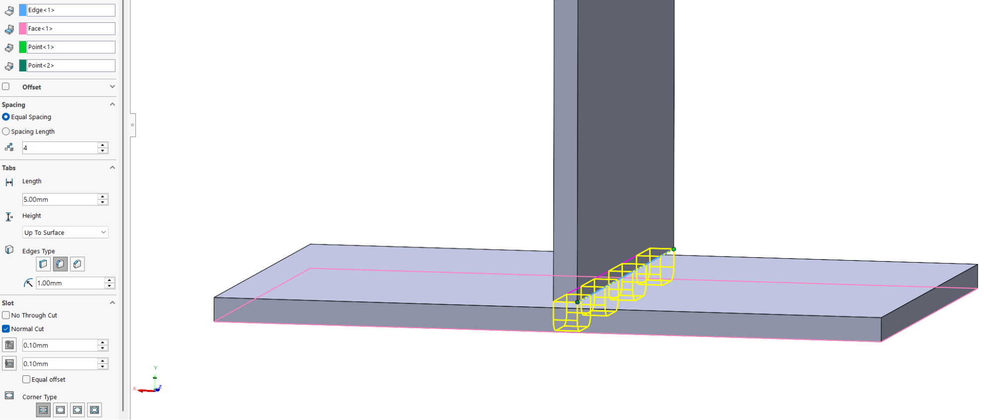
Tabs and slots can be built into CAD fairly easily with patterned features or built-in tools specifically for this application. SolidWorks has an option in the sheet metal tool that helps automate the design of these features, as shown in a brief walkthrough below:
- Create your base flanges, ensuring proper clearance.

- Create a tab and slot feature, specifying the edge, end face, length, and end type

- You now have your mating tab and slot features that will show in the flat pattern. You can add any additional rounds or chamfers to remove stress concentrations or break edges.

Tab and Slot Manufacturing Considerations
Once your design is finalized, the fabrication method of the sheet metal parts determines how precisely the interlocking features will fit together. Successful tab-and-slot assemblies depend heavily on cutting precision; laser cutting and waterjet cutting are the leading commercial methods because they deliver the tight tolerances required.
Laser Cutting
Laser cutting provides high precision (±0.1 mm) and clean edge quality, making it ideal for tab-and-slot parts in steel, aluminum, or stainless steel. Designers can typically apply slot clearances of 0.05–0.1 mm per side for an accurate, friction-fit assembly. The process also enables tight nesting for efficient material use.
Waterjet Cutting
Waterjet cutting is best suited for heat-sensitive or thicker materials (greater than 6 mm) since it avoids thermal distortion altogether. It produces a wider kerf and slightly tapered edge, so use the upper end of the clearance range (0.15–0.2 mm per side) to allow easy insertion without interference.
CNC Punching
CNC punching works well for simple geometries but is less suitable for detailed tab designs due to limited corner radius options and burr formation. It remains cost-effective for high-volume runs in mild steel, but for more intricate or high-precision parts, laser or waterjet cutting is preferred over punching. (CNC machining may also be used when tighter tolerances or 3D-milled features are required.)
Kerf Compensation in CAD
Most CAD programs define slots at nominal dimensions, but every cutting process removes additional material—known as the kerf—as it passes through. Kerf width depends on the process and material, but is typically 0.1–0.3 mm.
For critical fits, apply kerf compensation by enlarging slots by half the kerf width on each side to maintain proper engagement. For non-critical fits (e.g., loose mechanical assemblies or welded joints), standard nominal geometry is acceptable, as minor clearance variations do not affect function. Many modern CAM systems automatically compensate for kerf width, but always verify fit-up through test cuts or prototypes before production.

Tab and Slot Integration for Welding
When used in welded assemblies, tabs and slots act as self-fixturing features, temporarily holding components together and maintaining alignment while tack welds are applied. This improves efficiency and accuracy, particularly in thin-gauge or precision sheet metal assemblies.
Maintain 0.1–0.15 mm clearance per side to accommodate weld shrinkage of the base material as the joint cools, and avoid oversized slots that lead to thin weld sections or trapped molten metal. For parts requiring micron-level alignment, combine interlocking tabs with reference holes or pins. Alternate tack locations (e.g., Tab 1 and Tab 3, then Tab 2 and Tab 4) to balance thermal stress and reduce warping.
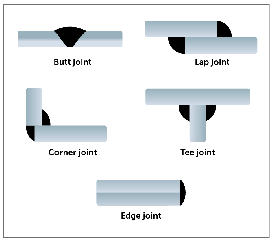
| Joint Type | Recommended Tab/Slot Design | Welding Notes |
| Corner Joint | Tabs located along 90° bends or outer edges | Maintains visual alignment of external faces and simplifies tack weld access. |
| Tee Joint | Slots positioned along the centerline of the base plate | Provides accurate vertical alignment of the perpendicular part and consistent weld penetration along the joint. |
| Lap Joint | Offset tabs and matching slots between overlapping plates | Enhances lateral rigidity and shear strength, but vertical movement can still occur unless supported by additional weld beads. |
| Butt Joint | Interlocking tabs across the joint line | Ensures edge-to-edge alignment for flush welding; ideal for flat panels requiring a continuous surface finish. |
Recommended Tab-and-Slot Configurations for Common Welded Joint Types

Tabs and Slots for Assembly Without Welding
Not all sheet metal assemblies require welding. Many product designers now use tabs and slots for purely mechanical or adhesive-based assembly, which can be ideal for modular products, prototypes, and consumer enclosures that require disassembly or low-heat joining.
When appropriately designed, tabs and slots act as alignment and engagement features, guiding components together while providing surface area for fasteners or bonding agents. This is especially valuable when integrating self-clinching hardware, adhesive bonding, or press-fit joints.
The role of tabs and slots is determined by the joining method.
In mechanical fastening, they provide precise alignment during bolting or riveting and are effective in applications such as electronics enclosures and bracket assemblies.
When used with adhesives, tabs and slots define the bond area and control bondline thickness; the slot depth sets the adhesive gap, typically ranging from 0.1 to 0.3 mm for structural adhesives. This method is commonly applied in lightweight panels and consumer products.
For press-fit joints, tabs and slots enable interference for friction locking and are often used for fixtures, temporary prototypes, and modular displays.
Common Design Mistakes and How to Avoid Them
| Mistake | Problem | Solution |
| Tabs too narrow | Weak engagement or bending failure during assembly. | Increase tab width to ≥1.2× material thickness for adequate strength and stiffness. |
| Tabs are misaligned with the bend | Distortion or cracking during forming; slot geometry becomes compressed. | Offset slots at least 1.5× material thickness away from the bend tangent line to maintain clearance. |
| Slot clearance insufficient | Difficult or impossible assembly; tabs bind during insertion. | Add 0.1–0.2 mm clearance per side (0.2–0.4 mm total) depending on the cutting process. |
| Excess tabs | Overconstrains the assembly, causing fit-up difficulty, thermal stress, and potential panel distortion during welding or press-fit assembly. | Use the minimum number needed for stability (typically 2–4 tabs per joint) to allow proper part relaxation and thermal expansion. |
| Poor nesting layout | High material waste and increased cost. | Share slot lines only when part orientations naturally align during nesting; avoid forced shared cuts that reduce yield. |
| Slot corner fillets too small | Localized stress concentration and potential micro-cracking at the slot base, especially near bends or welded edges. | Apply a fillet radius appropriate to material thickness and stress level, typically 0.1–0.2 mm for laser cutting and larger for thicker or high-strength alloys. Radiused corners are required regardless of the manufacturing process. |
| Sharp burrs at tab or slot edges | Prevents smooth insertion, damages coatings, or causes premature wear during assembly. | Specify deburring or edge finishing; laser cutting with nitrogen assist or fine waterjet cutting minimizes burr formation. |
Sheet Metal Slots and Tabs: Common Design Mistakes
Smarter Sheet Metal Design With Tabs and Slots
Integrating tabs and slots is one of the most efficient and reliable methods of self-locating assembly in sheet metal manufacturing. When engineered correctly, these features create repeatable, fixture-free assemblies that reduce setup time, rework, and cost. They align with DFM and DFA principles, improving accuracy while minimizing tooling and human error.
Fictiv’s team of manufacturing experts provides precision DFM feedback, integrated fastener installation, and rapid prototyping to validate tab-and-slot assemblies at speed. Explore the Sheet Metal Design Guide or browse customer case studies to see how top hardware companies accelerate production through Fictiv’s digital manufacturing platform.


