Time to read: 8 min
There are very few parts that function on their own—almost every design requires multiple pieces to be joined in some way to create a final product. When was the last time you had something other than a bottle opener that was a single, functional part?
When designing for a multi-part engineering build, there are extra considerations you need to keep in mind to make sure everything comes together as intended. Doing so will accelerate your build by allowing you to jump straight to the important stuff once your parts arrive: assembly, testing, and making something that works.
This article will cover a range of best practices around calling out design requirements, adding hardware installation, and adding surface finishes. Plus we’ll give you some tips on how to speed up your project by ordering through Fictiv.
Best Practices for Clearly Communicating Your Design Requirements
The first consideration in designing assembled parts is pretty simple: How are they going to be assembled? There are a myriad of ways to make two things attach together, but if you’re making a precise, strong, or re-configurable product, there are two main pieces of hardware you’ll use: screws and pins.
In general, pins are used for making sure parts are correctly located relative to one another, and screws are used for securely fastening them together. There are a lot of good resources online about how to design these types of connections (we’ve written a couple of articles on the subject), but to make sure your build goes smoothly, you also need to make sure these design requirements are clearly communicated with your supplier.
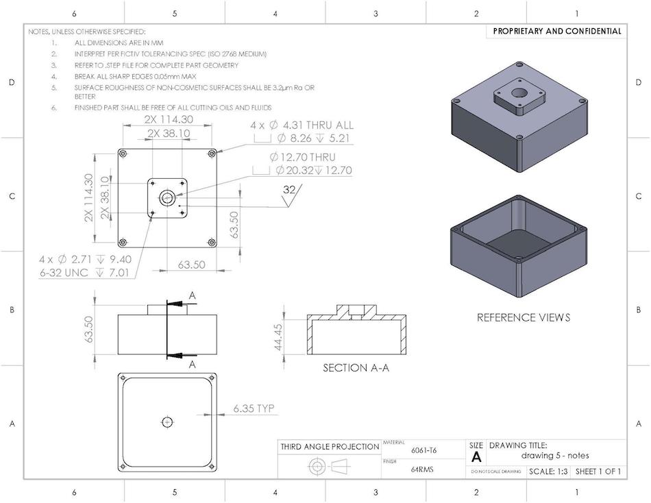
When using Fictiv, uploading a 2D drawing to your quote on the platform is the best way to do this. The following tips will help ensure that your drawing reflects your intended design.
1. Give a Tolerance
The phrase “slip fit” and “press fit” are pretty universal and intuitive, but they’re not numeric tolerances. In simple cases, where it’s OK to leave the sizing of a dowel pin hole up to the discretion of the machinist, using these callouts for a dowel pin hole is fine. But if you have a lot of parts that may need to be made at multiple shops, or have press fit holes close to the edge of a part, a specific tolerance can ensure consistency and prevent accidental deformation of your part.
Providing either a numeric tolerance (ex .125” +/-.002) or a tolerance class like those found in ISO 286 (ex. 5 mm H7) is the way to go. With a drawing including, Fictiv can hold tolerances as tight as +/- 0.0002”. You can find our full tolerance standards here.
2. Be Clear with Your Callouts
Under-specified callouts in a drawing can lead to confusion about the intended nature of a hole. For example, the phrase “M6” on a drawing could mean three different things: an M6x1 threaded hole, an M6 clearance hole, or a hole toleranced to M6 per ISO 286. And we’ve seen drawings that have all three of these types of features on the same part. Giving a fully defined callout, like “M6x1 6G threaded hole”, “M6 clearance”, or “ 6 mm M6 (-.001/-.009)” will ensure the parts are made to the specifications you need.
3. Consider Your Hole Depths
Make sure to consider the depths of the holes in your part, not just the diameters. Blind threaded holes for a screw, for instance, need additional depth below where the thread ends to allow for tool clearance. So if you need 0.5” of thread for a screw to fit in to, the hole needs to be deeper than 0.5”. If you’re pressing in dowel pins, there also needs to be additional depth below the bottom of the pin, to allow space for the air stuck inside the hole to be compressed.
4. Label Holes
In large parts with lots of different types of holes, such as a base plate that has multiple parts pinned and screwed to it, it can be difficult to keep track of every hole. A callout such as “¼-20 thread, 35 places” can be confusing, unless all of those 35 holes are in a clear, easy to see pattern. Using hole tables or lettering the different types of holes on a drawing (e.g., “All holes labeled A are ¼-20 threads, all holes labeled B are .25”-0/-.002), can be a much cleaner way to accomplish this.
Adding Hardware to Your Machined Parts
After making sure your parts will be correctly machined for your required hardware, you need to actually get it installed.
Most assembly hardware can be installed by hand, so it’s not uncommon for engineers to try and do so themselves. However, installation often requires expensive hand tools, some finesse, and the time to install them properly. Particularly when there are multiple pieces of hardware to install, having the shop that is making the part also take care of hardware installation improves quality and speeds up your build by getting you parts that are ready to assemble out of the box.
Adding hardware to a part can be easily done through the Fictiv platform by adding the requirements to a 2D drawing, just like you would for calling out other special requirements. The following tips can help you make the most of hardware installation.
1. Be Specific
The most important thing to include is a clear definition of what hardware needs to be installed. The easiest way to do this is to give the McMaster Carr part number for what it is you want installed. McMaster Carr is currently Fictiv’s source for hardware, as their quick turnaround times ensure our manufacturing partners can meet our quoted lead times.
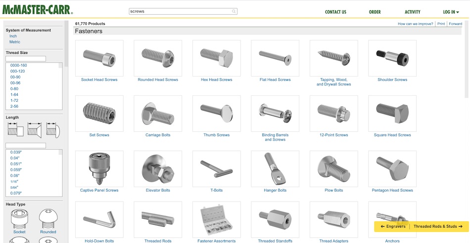
In lieu of an exact part number, a detailed description can be provided, such as “.125” dowel pin, .8125” length, 4140 alloy steel”.
2. Pins Need Tolerances, Too
If you have dowel pins installed into your part, specify how far proud (above) the surface they should be. This ensures they’ll fit properly in the mating holes or slots.
3. Use Threaded Inserts
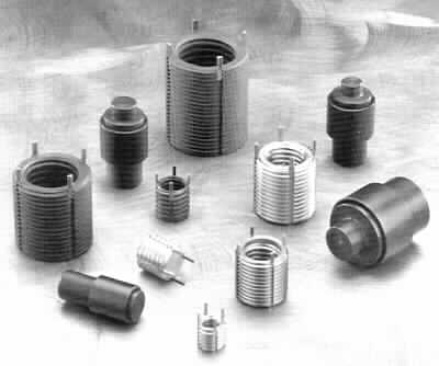
Threaded inserts, such as helicoils or key inserts, are usually advertised as being used for repairing faulty threads. However, installing them into a soft metal part will give your screws a harder surface to thread into. If you plan to be taking your assembly apart multiple times, this can preemptively prevent threads from getting worn down or stripped.
4. Remove Extra Bodies From Your CAD
Depending on how you make your design, you may have CAD files of your part that have hardware modeled in as separate bodies. While these can be very helpful during design, they cause difficulties during machining. Any extra bodies should be removed from your part files before uploading them for a quote.
Note that there are limits on what hardware Fictiv can currently install: we will only install off-the- shelf components, and only components that stay static and permanent inside the part. This means that we can’t install fabricated parts (such as custom diameter or length pins), removable hardware (such as screws), or moving hardware (such as bearings).
Best Practices For Adding Surface Finishing To Your Parts
Finally, to really make your pieces feel like finished parts, you may want to add some type of surface finishing. The most common finishing process is anodizing aluminum for extra hardness or to add color.
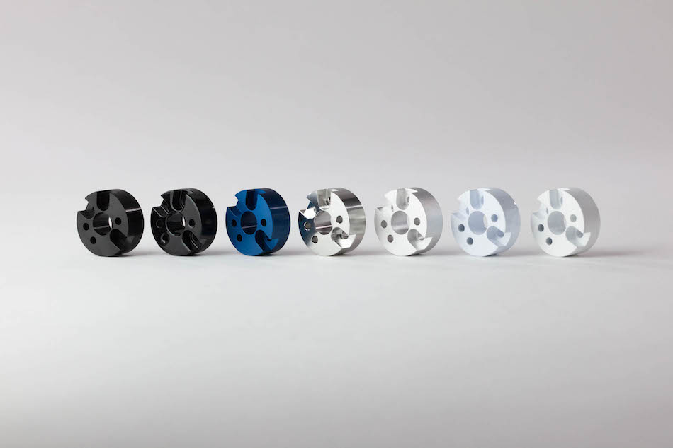
Media blasting and anodizing aluminum can give it a very professional, finished look (for reference, MacBook bodies are media blasted and anodized).
Whether your surface finishing is for functional or aesthetic reasons, there are several options that can be configured for in the Fictiv platform. You can see the full range of finishing options here. For complex designs, multiple finishes may even be combined.
The following tips can help you make sure your parts come out the way you want and are ready for your build.
1. How to Call Out Masking for Different Finishes Per Surface
One reason to have multiple surface finishes is because certain surfaces need one finish, while other surfaces need another. For example, a part may need conductive Chem film or Alodine™ on some surfaces to attach grounding components, while other surfaces need more wear-resistant anodize.
This can be accomplished by masking certain surfaces between processes, but the request needs to be called out very clearly. Ideally a colored image, showing which surfaces need which finish, should be added to the drawing. Callouts like “anodize all surfaces in this view” can lead to confusion about what to do with side walls, through holes, or outside edges.
2. Account for Hardware Installation
The chemical tanks used to plate parts with different finishes can only have certain materials in them; the biggest restriction being that anodizing tanks can’t have steel in them. Thus, if an aluminum part has steel inserts, they have to be done after anodizing.
This means the parts will need to go back to the machine shop after anodizing but has the advantage of letting the machine shop clean up the part before installing hardware, ensuring the installation goes smoothly.
3. Protect Tolerances
While most surface finishes don’t impact the geometry of a part by much, they can influence very tight tolerances and small features. Reamed holes, like those for a slip fit with a dowel pin, should be masked to ensure a proper fit. Small threads can also benefit from being masked, otherwise they may be too tight after anodizing.
Noting in a drawing where this is allowable will help remove any confusion and ensure parts fit the way you want them to.
4. Note Cosmetically Important Surfaces
Plating a part in a different material, like anodizing or nickel plating, requires parts to be suspended on some type of rack, so that they can be hung in a tank of chemicals. This means that these types of processes will leave “rack marks” on parts, which are small, unplated areas where the part was in contact with the rack. While these marks are usually unavoidable, specifying which surfaces need to be free of rack marks, or which ones can have rack marks, will help ensure they aren’t placed on cosmetic or important surfaces.
The Final Reward: Getting Your Parts In-Hand, Build-Ready
Once all your designs and drawings are nailed down, it’s time to order them. On the Fictiv platform, uploading a drawing with your requirements called out is easy, and surface finishes can be configured for each part directly.
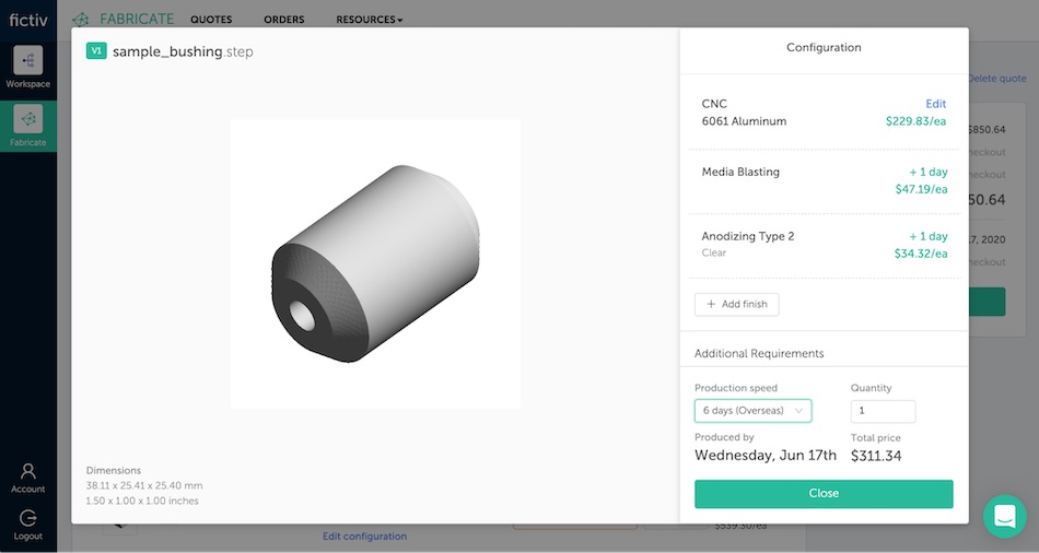
Finishes will only be added in an order and combination that is manufacturable, and any concerns about hardware or masking will be flagged in the manufacturability feedback in your quote before checkout. Then, your parts show up ready to use, so you can quickly get to what you do best.
To try it out for yourself, create a free account here!


