




Time to read: 8 min
Here’s a common mistake: an engineer designs a structural bracket using FDM 3D printing, runs FEA with the tensile strength from the material datasheet, and predicts a comfortable factor of safety. The printed part fails at a fraction of the predicted load. The material and analysis were correct, but the FEA assumed isotropic material properties for a part that is anisotropic in reality, and that mismatch between the model and the physical part was the problem.
This scenario plays out regularly across 3D printing, metal manufacturing, and composite design. Understanding which materials and processes produce anisotropic parts, and what the design implications are, is one of the most important materials concepts for engineers working across multiple manufacturing processes.
Anisotropic and Isotropic Materials Defined
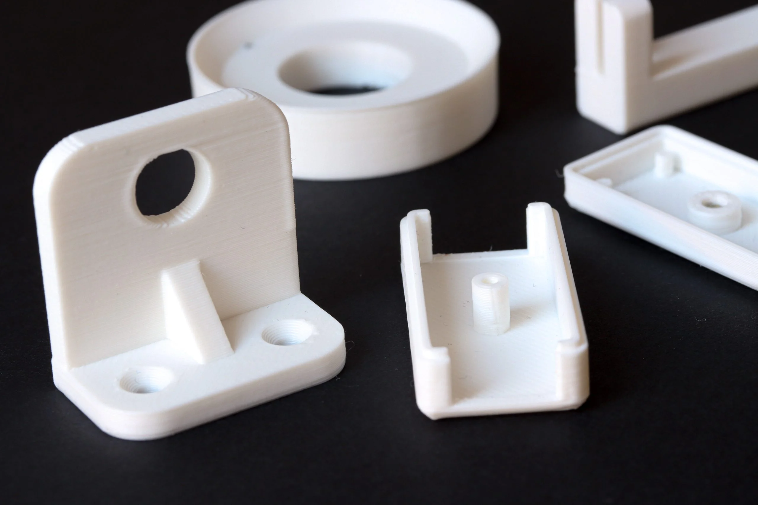
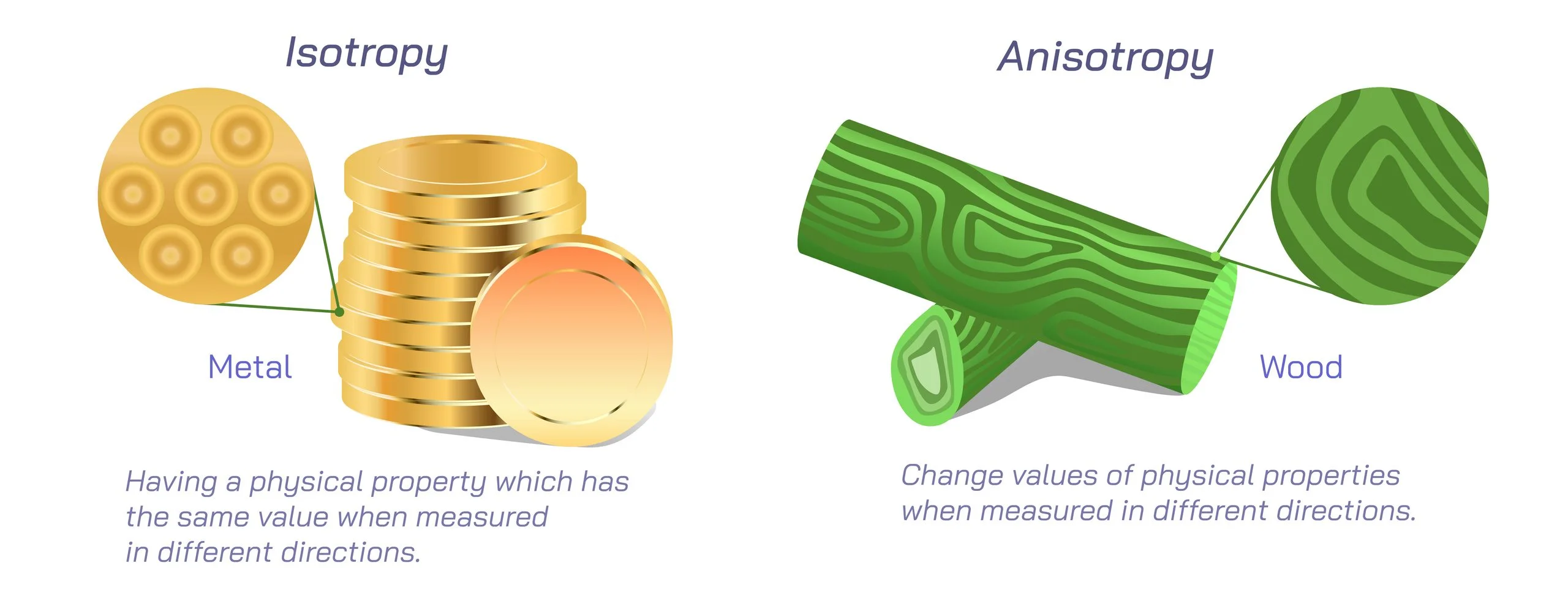
An isotropic material has the same mechanical properties in all directions. Cut a tensile specimen from any orientation and you get the same test result. An anisotropic material has different properties in different directions, making the orientation of the test specimen matter.
Most cast metals, most CNC-machined parts from wrought stock (in-plane), and most unfilled injection-molded plastics are isotropic or close enough to isotropic that standard analysis methods apply without correction. On the other hand, FDM-printed parts, rolled sheet metal, fiber- or glass-filled injection-molded resins, and CFRP are meaningfully anisotropic: direction-dependent properties are built into the material or the process that created it.
A related term worth knowing: orthotropy is a specific type of anisotropy with three mutually perpendicular axes of symmetry, each with different properties. Most structural composites and rolled metals are orthotropic rather than generally anisotropic.
In practice, engineers use “anisotropic” loosely to mean orthotropic when discussing manufacturing materials. The distinction matters primarily for FEA setup, where orthotropic material models require nine independent elastic constants rather than two for isotropic materials.
Anisotropy in Manufacturing Processes
FDM (3D Printing)
FDM printed parts are anisotropic because layer-by-layer deposition creates interfaces between layers that have lower bond strength than the material within each layer. The Z direction (perpendicular to the build plane) is consistently weaker than X or Y. Typical tensile strength in Z is 15–40% lower than in XY depending on material, layer height, print temperature, and machine calibration.
This is a fundamental characteristic of the process, not a defect or a quality problem. The interlayer bond in FDM forms as adjacent beads partially fuse during printing, and it’s inherently weaker than the base material, regardless of print quality. FEA of FDM structural parts should use orthotropic material properties with a Z-direction knockdown applied, not the isotropic tensile strength from the manufacturer’s datasheet. Most FDM material datasheets report XY-direction properties only. Check whether Z-direction data is available for the specific material and use it if the loading direction is not purely in-plane.
SLS and MJF (3D Printing)
Powder bed fusion processes produce parts that are significantly more isotropic than FDM. The sintering or fusion mechanism creates more uniform bonding across all directions rather than a layered structure with defined interfaces. SLS nylon parts typically show Z-direction strength 80–95% of XY-direction strength, which is close enough to isotropic that standard isotropic FEA is acceptable for most structural applications.
This is one of the primary engineering advantages of SLS and MJF over FDM for functional structural parts: the assumptions used in isotropic analysis are much more accurate, reducing the risk of underpredicting Z-direction loads.
Rolled and Wrought Metals
Rolling, drawing, and extrusion align the grain structure of the metal in the working direction, producing mild but real anisotropy. In steel and aluminum sheet, the rolling direction is typically 5–15% stronger and tougher than the transverse direction. The through-thickness direction (short transverse) is the weakest in most rolled products.
Grain direction matters most in three situations: forming operations, where bends perpendicular to the rolling direction require larger bend radii to avoid cracking; fatigue-critical applications, where crack propagation is faster transverse to the grain; and high-strength alloys like 7075-T6, where the short-transverse direction has substantially lower fracture toughness than the longitudinal direction, which is relevant for thick plate applications in aerospace structure.
Cast Metals (Die Casting, Investment Casting, and Gravity Casting)
Cast metals are the closest thing to a true isotropic baseline on this list. Solidification from a liquid produces a fine, non-directional grain structure, so bulk stiffness and strength are nearly equal in all directions, and standard isotropic FEA is appropriate for the vast majority of cast parts.
Two effects introduce local (not bulk) anisotropy, and both are worth checking for during inspection:
Flow lines form where two melt fronts meet last inside the mold, similar in effect to a weld line in injection molding, and they create a local plane of reduced strength, usually positioned farthest from the gate.
Porosity, more common in high-pressure die casting (HPDC) than in investment or gravity casting, is often distributed unevenly through a part’s cross-section; because porosity concentrates stress, it can produce a direction-dependent reduction in fatigue strength even when the surrounding bulk material is isotropic.
Neither effect shows up on a standard material datasheet, which reports bulk, pore-free properties. Gate location and process parameters, not the alloy itself, determine where these local weak zones land in the finished part.
Composites (CFRP, Fiberglass, Woven Fabrics)
CFRP is the most anisotropic material engineers commonly specify. Carbon fibers have very high stiffness and strength along their length (a modulus of around 230 GPa for standard-modulus fiber) and substantially lower properties transverse to the fiber direction. The ratio between fiber-direction and transverse properties is typically 10:1 to 20:1 for stiffness and 5:1 to 10:1 for strength.
The composite layup schedule is the arrangement of fiber orientations through the laminate thickness that determines the directional properties of the finished part. A unidirectional layup is highly anisotropic, carrying load efficiently only along the fiber direction. A quasi-isotropic layup (fibers at 0/45/90/−45) approaches isotropy in-plane, distributing stiffness more evenly across directions at the cost of peak performance in any single direction. Engineers specifying CFRP parts must work from the layup schedule, not from raw fiber properties, to make accurate stiffness and strength predictions.
Process and Material Isotropy Comparison
| Process / material | Isotropy level | Primary anisotropy direction | Design implication |
| FDM / FFF | Anisotropic | Z-direction significantly weaker (15–40%) | Orient parts so primary loads are in XY; use Z-direction knockdown in FEA |
| SLS / MJF nylon | Near-isotropic | Mild Z-direction (5–20%) | Isotropic FEA acceptable for most applications |
| Rolled steel / aluminum sheet | Mildly anisotropic | Rolling direction stronger | Orient bends and fatigue-critical features to account for grain direction |
| Drawn / extruded bar and plate | Mildly anisotropic | Longitudinal direction strongest | Through-thickness and short-transverse properties lower in thick sections |
| Cast metals (die casting, investment) | Near-isotropic bulk | Local flow lines / porosity, not bulk-directional | Standard isotropic FEA acceptable; check flow-line location and porosity in fatigue-critical zones |
| Injection molded plastics (unfilled) | Near-isotropic | Mild at weld lines | Weld lines are local weaknesses; avoid in primary load paths |
| Injection molded plastics (glass/fiber-filled) | Anisotropic | Fiber orientation follows flow direction | Flow-direction properties stronger than cross-flow; verify with fill simulation for structural parts |
| CFRP—unidirectional | Highly anisotropic | Fiber direction vs. transverse (10–20x stiffness difference) | Layup schedule must match load direction; laminate analysis required |
| CFRP—quasi-isotropic | Near-isotropic in-plane | Through-thickness weak | In-plane isotropic FEA acceptable; delamination risk in Z direction |
Design Implications: What to Do With This Knowledge
Process selection for structural applications. If isotropic properties are required for predictable structural performance, die casting, CNC machining from wrought or cast stock, SLS/MJF, or injection molding are better choices than FDM. If CFRP is specified for weight efficiency, the layup schedule must be designed for the load case, not left as a manufacturing detail, and reviewed by someone with experience in laminate analysis.
FDM build orientation and FEA inputs. Review every FDM structural part’s build orientation against its primary load direction before printing, and orient it so the primary tensile load runs in XY rather than Z. Where Z-direction loading can’t be avoided, don’t carry over the isotropic datasheet value. Use orthotropic properties instead (E_z is typically 0.6–0.85 × E_xy for FDM nylon, with similar knockdown in ultimate strength), or apply a conservative factor of safety to Z-direction stresses if orthotropic data isn’t available.
Grain direction in sheet metal. Specify grain direction on the drawing when it matters: “grain direction parallel to long axis” for parts where bend lines need to be perpendicular to grain, or for fatigue-critical sheet metal parts where crack propagation direction is important. Many fabricators will not track grain direction unless specified.
Gate location and porosity in castings. For fatigue-critical die cast parts, ask where the gate and last-fill zones are and whether those locations overlap with high-stress areas in the FEA model. This is a process and tooling conversation, not a datasheet lookup.
How to Read Material Datasheets Correctly
Material datasheets and process specifications encode the anisotropy question in ways that are easy to miss:
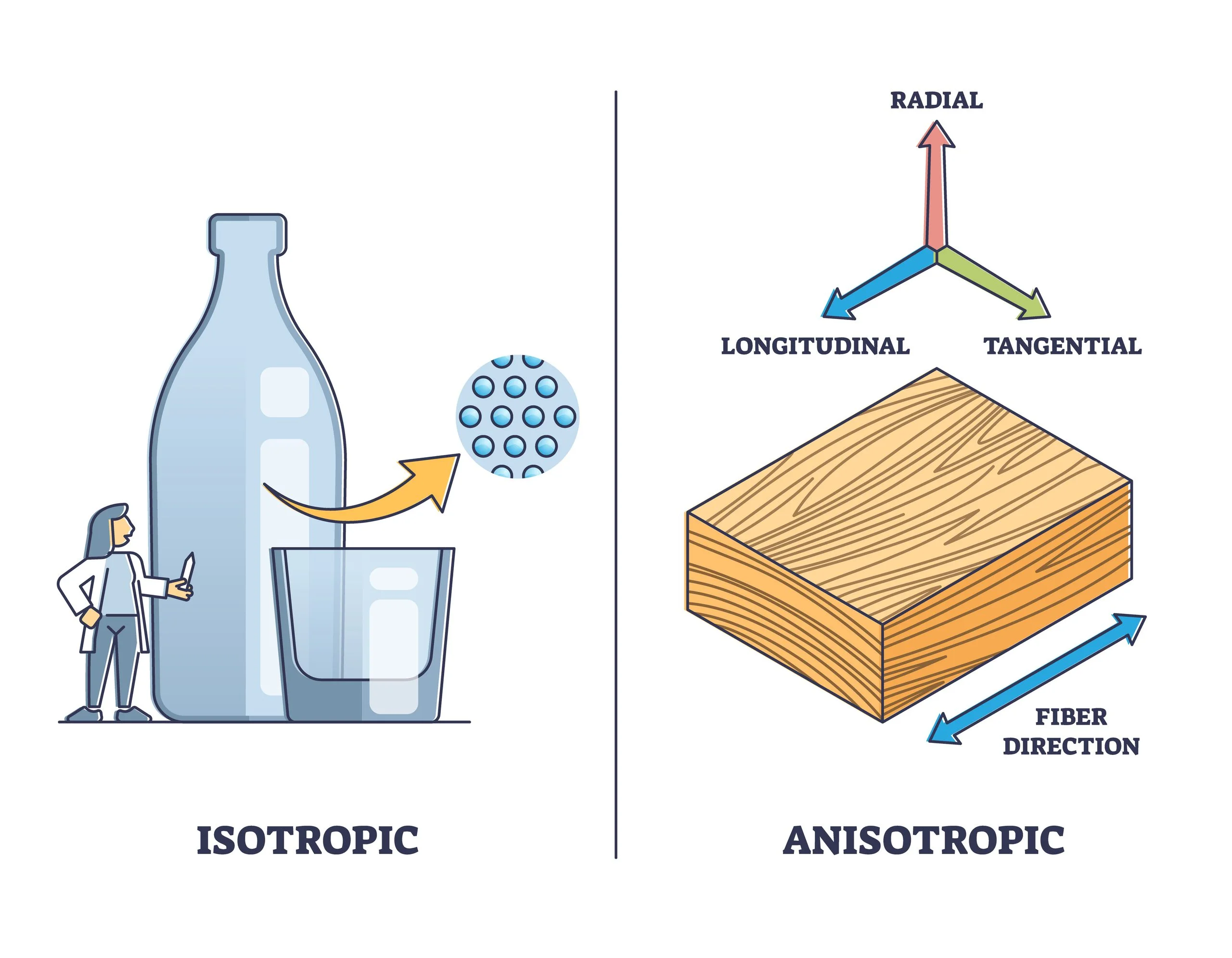
Isotropic materials report a single value for tensile strength, modulus, and elongation. It applies in all directions without qualification.
FDM material datasheets often report XY and Z properties separately where the manufacturer has measured both. Check whether the reported tensile strength applies only to the XY direction. This is the stronger direction, and using it for Z-direction loading is non-conservative. Some datasheets footnote this; others do not.
Cast metal datasheets report bulk, pore-free properties measured from a test coupon, not the local properties at a flow line or a porosity cluster. They’re a reasonable starting point for isotropic FEA but won’t flag the local weak zones described above.
CFRP material datasheets report 0° (fiber direction) and 90° (transverse) properties for unidirectional material. Laminate properties must be calculated from layup analysis using classical lamination theory or FEA—they cannot be read directly from the fiber datasheet.
Rolled metal datasheets typically report longitudinal (rolling direction) properties. Through-thickness and transverse properties are lower, particularly for fracture toughness in high-strength alloys. For thick-section applications or fracture-critical components, look for short-transverse property data in the alloy specification rather than the standard datasheet.
Don’t have time to dig through a datasheet?
Materials AI can answer direction-specific property questions directly from Fictiv’s materials database.
Upload your part and get material suggestions right in the platform during quoting.
Talk to a Fictiv expert about your project, or upload your parts to start a free quote.