





Time to read: 12 min
Most engineers have a solid feel for what CNC machining can do. But far fewer have a clear picture of what to do when conventional CNC process capabilities are exceeded by the need for tighter tolerances, finer surface finishes, or hardened work material that quickly wears through machine tools. When that happens, manufacturing engineers move to grinding, lapping, and honing technologies to achieve the required results.
Precision grinding routinely holds tolerances of ±0.005 mm or better and surface finishes below Ra 0.4 μm, levels that CNC milling and turning cannot maintain on a repeatable basis in production at higher volumes. This is when a cost-benefit analysis can tip from milling to grinding. After that, it’s all about knowing which grinding process to specify, and how to call it out on a drawing so your supplier interprets it correctly and builds it to match what you had in mind.
Precision grinding covers a family of abrasive processes: surface, cylindrical, centerless, internal, and jig grinding. Each one solves a specific geometry problem that milling and turning can’t reliably address at production tolerances.
This article will discuss the main types of precision grinding, what they can achieve, and how to specify grinding callouts on a drawing.

What CNC Machining Can and Cannot Achieve
CNC milling and turning are excellent processes right up until a feature demands tighter control than the process can hold repeatably. At that point, grinding is a better choice.
Well-set-up CNC milling routinely holds a tolerance of ±0.025 mm on most features. Tighter tolerances are achievable with care, though not reliably below ±0.01 mm across a production run. Some shops can push an individual feature tighter still, into the low single-digit micron range, with the right machine, fixture, and inspection loop, but that’s a best-case result. The surface finish produced by finish milling typically lands at Ra 0.8 to 1.6 μm. You can push it down to Ra 0.4 μm with fine feeds and sharp tooling, but holding that consistently across a batch is a different problem entirely.
Even with 5-axis CNC machining capability, achievable tolerance and finish come down to tool deflection, setup rigidity, and cutting rate parameters. CNC machining reaches its limit in applications such as bearing seats needing a consistent ±0.005 mm diameter, sealing surfaces that need Ra 0.4 μm or flatter every time, gear tooth profiles with strict involute form requirements, and flat mating surfaces requiring flatness under 0.01 mm, a geometric-form spec distinct from the Ra requirement above.
Grinding is used wherever tolerance, surface finish, or form accuracy (flatness, roundness, cylindricity) on a functional surface needs process stability that milling and turning can’t effectively deliver at scale.
The Main Types of Precision Grinding
Grinding consists of a family of processes, and each type solves a specific geometry problem. Picking the wrong process can either waste money or leave you with finished parts that don’t meet customer specifications.
Surface Grinding
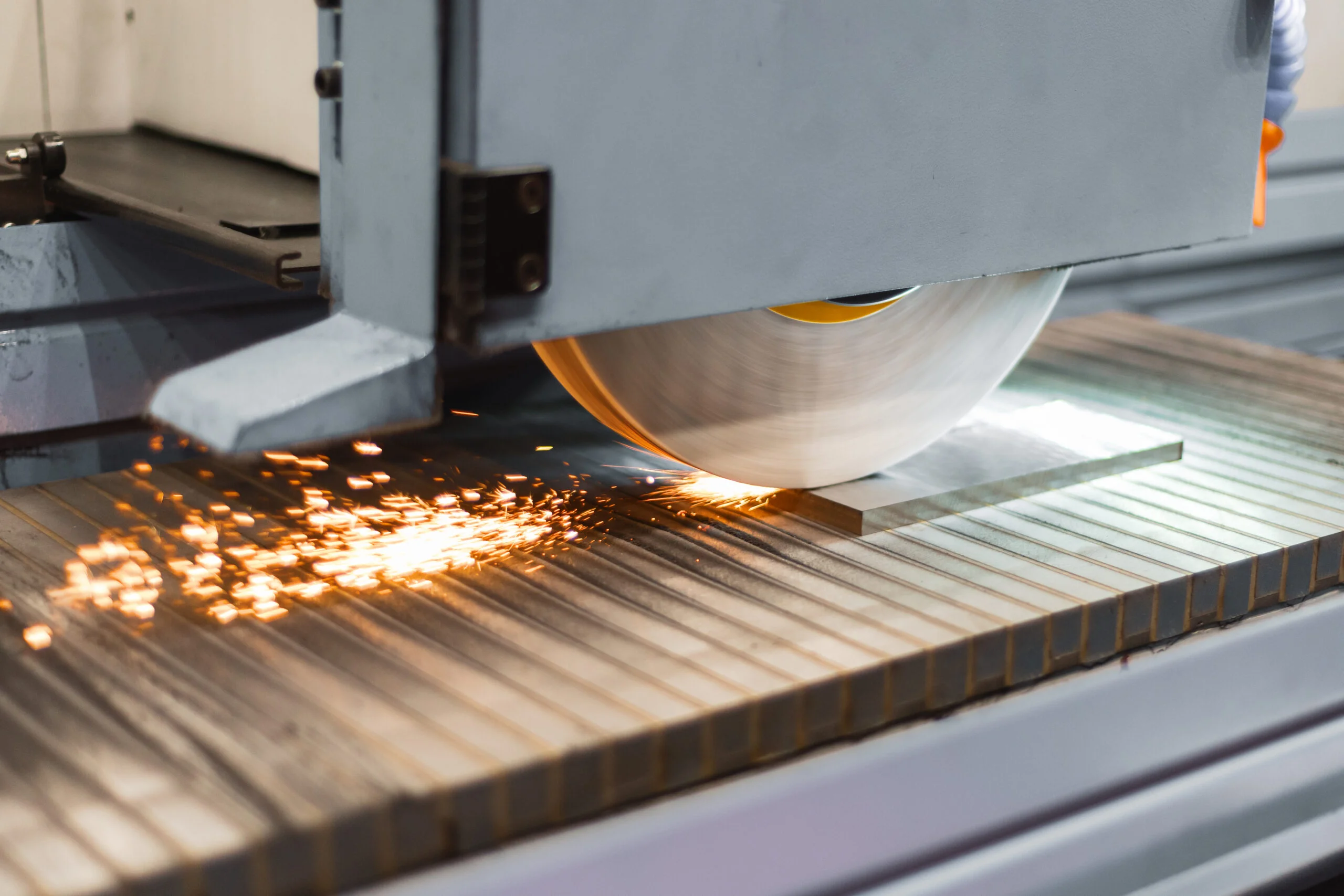
Surface grinding is accomplished by a rotating abrasive wheel that traverses the workpiece to produce a flat, smooth face. Expect ±0.005 mm or better on thickness and flatness, with surface finish in the Ra 0.1 to 0.4 μm range. It’s the go-to method to use for mating surfaces, sealing faces, tooling plates, parallels, and precision fixtures. However, it is not applicable to cylindrical or complex geometry.
Cylindrical Grinding (OD Grinding)
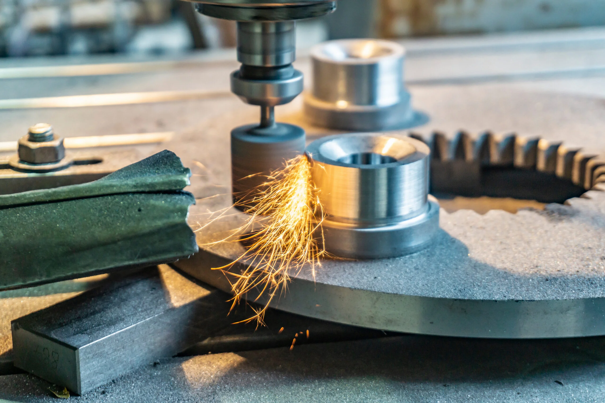
In cylindrical grinding, the workpiece rotates between centers or in a chuck, while the wheel grinds the outer diameter. This process produces precise diameters with excellent roundness. Typical tolerances range from ±0.002 to 0.005 mm on the diameter, with an Ra 0.1 to 0.4 μm surface finish. Bearing journals, shaft diameters, gauge plugs, and precision pins are typical cylindrical grinding candidates.
Centerless Grinding
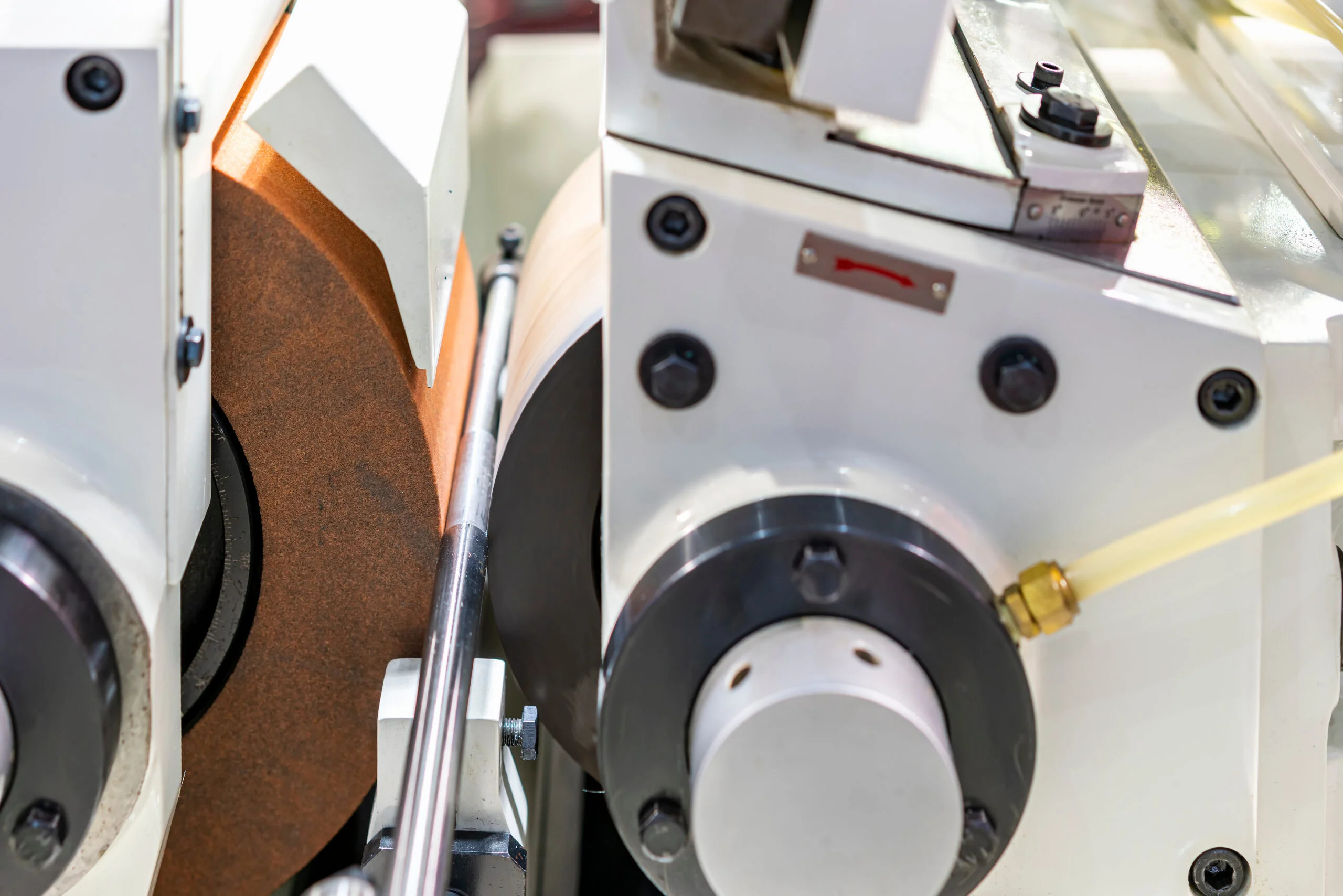
Centerless grinding uses no centers and no chuck. The workpiece rides on a work rest blade between a regulating wheel and a grinding wheel, which makes it fast for long, consistent-diameter parts. This technique yields tolerances around ±0.002 to 0.005 mm in diameter. It’s the right call for high production of rods, pins, shafts, and fasteners where the length-to-diameter ratio makes chuck-based cylindrical grinding a hassle.
Internal Grinding (ID Grinding)
Internal grinding is used to remove material from the bore rather than the outside diameter of a workpiece, typically holding a ±0.005 mm accuracy. Bearing housings, precision bores in gears and pulleys, and sealing bore surfaces are the usual candidates for this process. Other internal cutting processes, such as boring or reaming, may get you close to what you need. If a housing bore needs a high-precision H6 or H7 tolerance, this is the process that gets you there.
Jig Grinding
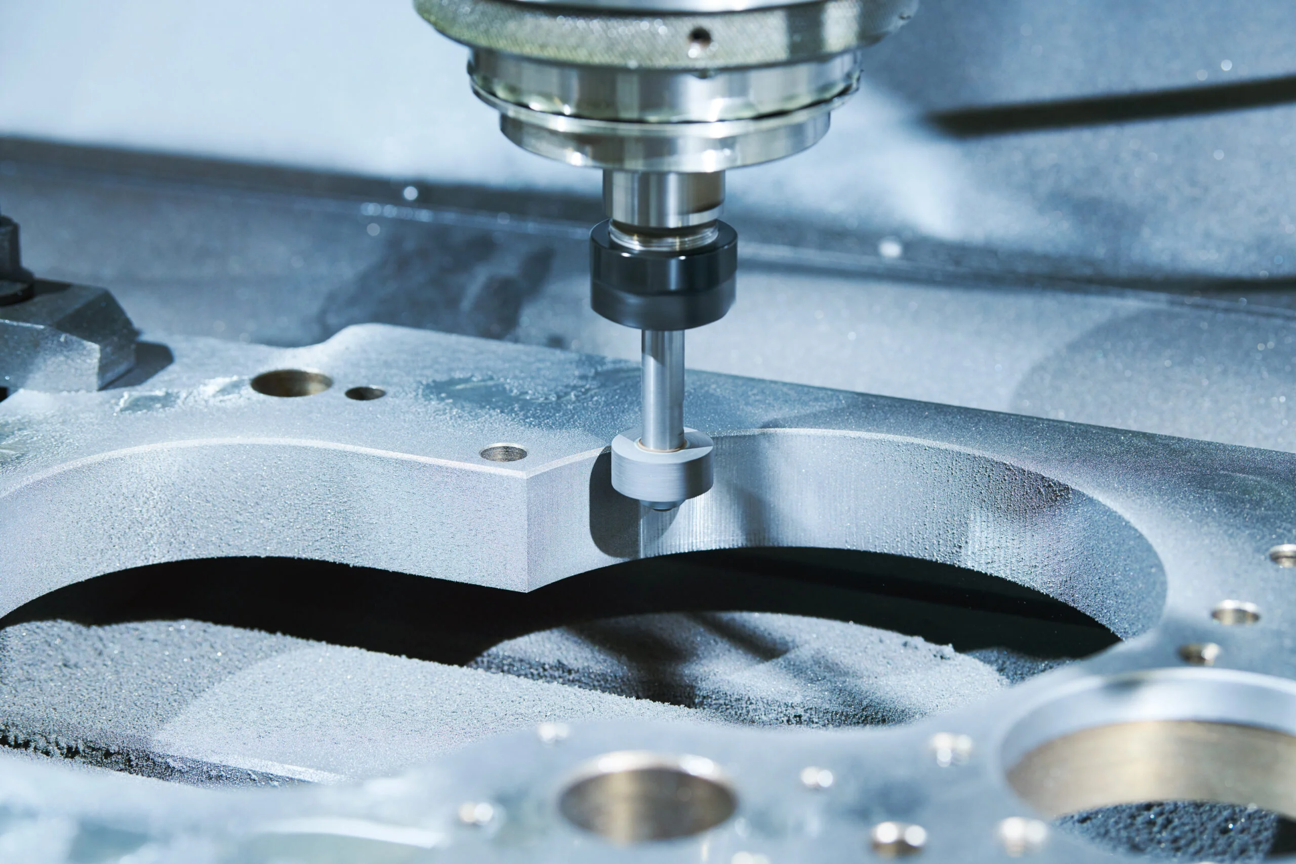
Jig grinding is the process of CNC-controlled coordinate grinding for complex 2D profiles and hole locations. It is capable of ±0.002 mm or tighter positional accuracy. This technique may be employed for finishing precision dies, hardened tooling with complex profiles, and aerospace or medical parts with demanding positional requirements, all applications with tight tolerance requirements.
Precision Grinding Tolerance and Surface Finish Reference
For features that aren’t individually toleranced, the title block usually defaults to a general callout like the ISO 2768 Tolerance Standard. The figures below show what each process can hold once a feature is specifically called out for grinding, tighter than the ISO 2768 general tolerance class covers by default.
Dimensional Tolerance and Surface Finish of Various Grinding Processes
| Process | Dimensional Tolerance | Surface Finish (Ra) | Typical Application |
|---|---|---|---|
| CNC milling (finish) | ±0.025 mm | 0.8 to 1.6 μm | General precision machined parts |
| CNC turning (finish) | ±0.013 mm | 0.4 to 0.8 μm | Precision turned diameters |
| Surface grinding | ±0.005 mm flatness | 0.1 to 0.4 μm | Mating surfaces, sealing faces |
| Cylindrical grinding | ±0.002 to 0.005 mm dia. | 0.1 to 0.4 μm | Bearing journals, precision shafts |
| Internal grinding | ±0.005 mm dia. | 0.1 to 0.4 μm | Bearing housings, precision bores |
| Jig grinding | ±0.002 mm positional | 0.2 to 0.4 μm | Tooling, hardened precision parts |
| Lapping (reference) | ±0.001 mm | 0.025 to 0.1 μm | Gauge blocks, optical flats, ultra-precision |
When To Specify Grinding, and When Not To
Specify grinding when part function demands it. Bearing fits on IT5/IT6 shafts or H6/H7 housing bores, the kind of engineering fits and tolerances that show up on nearly every bearing print, almost always need grinding. Sealing surfaces where leak tightness depends on surface finish need it. Hardened parts above 58 HRC, which are too difficult to machine economically with a mill, need it too.
Don’t specify grinding just because it sounds more precise. A callout for grinding on a feature that careful CNC machining could have satisfied on its own is the single most common mistake we see on drawings. Grinding doesn’t just increase cost; it adds a whole secondary operation with its own setup and run time, typically raising expenses 20 to 50% on top of the machining cost for that feature. The extra cost increment can be even more on small or complex parts. Specify grinding only when the resulting tighter tolerances and better surface finish meet a functional need.
Not sure whether your tolerance calls for grinding, or whether precision CNC machining can get you there on its own? Talk to a Fictiv engineer about your specific print for guidance on what it takes to hit it and what that means for cost and lead time.
Grinding Burn: Heat Control and Metallurgical Damage
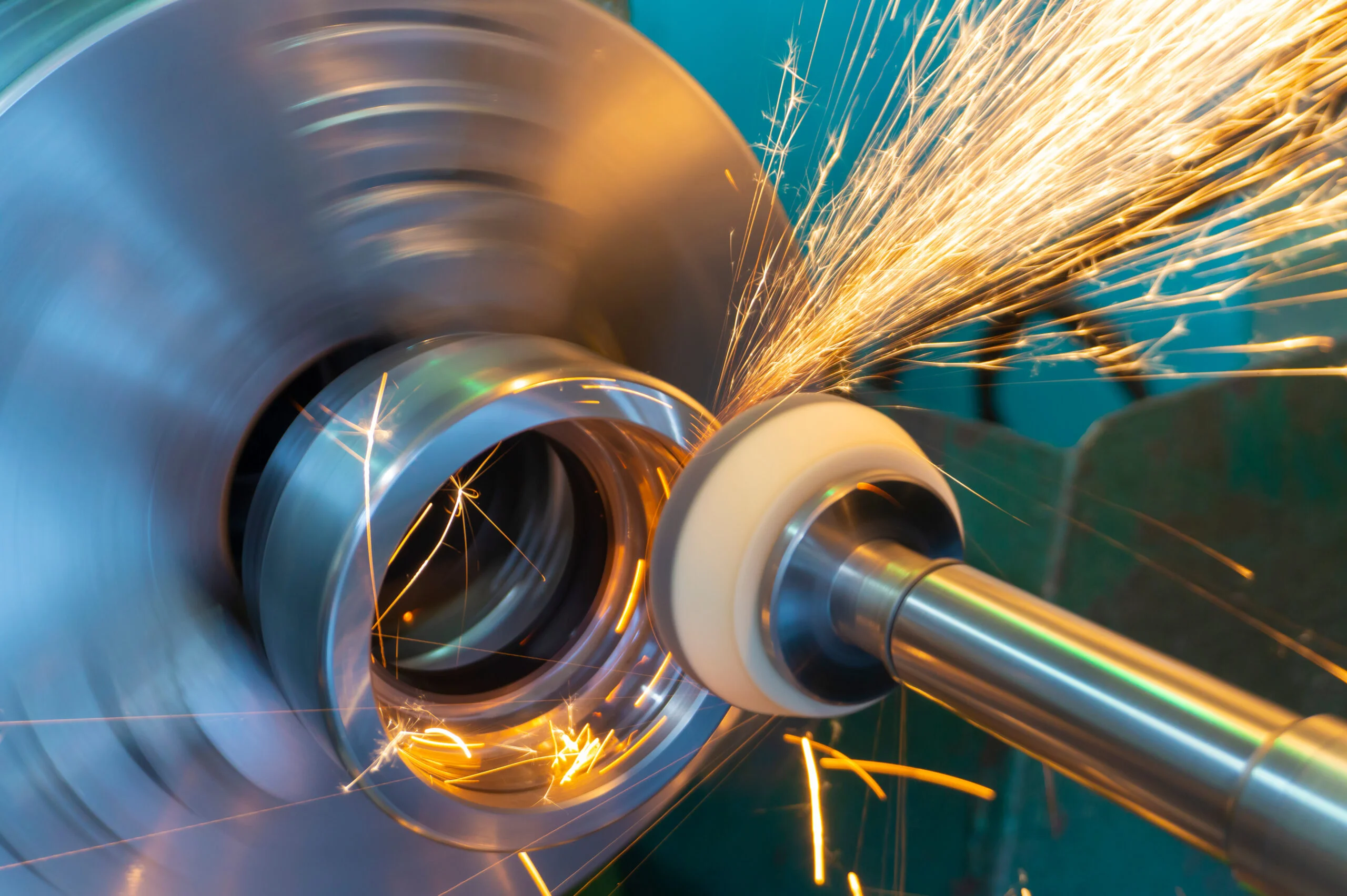
Grinding generates heat at the wheel-workpiece contact zone, and aggressive material removal rates or inadequate coolant flow can leave enough of that heat in the part to alter its surface metallurgy.
The hot surface layer cools and contracts against the still-cool bulk material beneath it, which leaves the surface in tension. In hardened steels, that heat can either re-temper the surface, softening it, or re-harden it into a layer that’s harder than the base material but brittle and prone to microcracking. Both conditions reduce fatigue life, just through opposite hardness effects.
For aerospace, medical device, and high-cycle bearing applications, call out a metallurgical inspection to confirm the ground surface came through unchanged. Barkhausen noise analysis (BNA) and X-ray diffraction (XRD) are the methods to specify for this: both are objective, repeatable, and can be automated on a production line, and BNA can even read through coatings. Nital etch inspection is the older, cheaper method that reveals overheated areas as dark patches after acid etching, but it removes a microscopic amount of material and is considered less reliable by most metallurgical labs today. Whatever inspection method you specify, put it on the drawing or in the control plan. A verbal agreement with the shop does not travel with the part.
How To Specify Grinding on a Drawing
For surface finish, put the Ra value directly on the surface that needs grinding using the standard surface roughness specification symbol. Ra 0.4 μm is a common ground surface spec. Ra 0.2 μm suits precision sealing surfaces, and Ra 0.1 μm is reserved for the highest precision work.
For cylindrical grinding, specify the diameter tolerance with an ISO designation like ø25h5, or spell out an explicit range such as ø25.000/24.995 mm. The shaft and hole fit system is the clearest way to communicate the intended fit to the grinding operator.
For surface grinding, apply a flatness symbol using standard geometric dimensioning and tolerancing notation, with the actual tolerance value called out. A vague notation like “Grind flat” without a number invites every supplier to interpret it differently.
If the part gets ground after heat treatment, say so on the drawing, and make sure the pre-heat-treat machining allowance accounts for material removed during grinding, usually 0.1 to 0.5 mm per surface depending on expected distortion. This is also typically where a note on material traceability belongs, since heat-treat lot data needs to carry through to final inspection.
For anything below Ra 0.2 μm, add a note requesting wheel specifications or a pre-production sample for approval. Final surface finish at that level depends as much on wheel condition, dressing frequency, and coolant management as it does on the wheel spec itself.
Working on a part with a tight tolerance or surface finish call-out? Fictiv’s manufacturing network covers surface grinding, cylindrical grinding, and post-heat-treat processing as part of complete CNC programs. Upload your part for a quote and DFM review and we’ll help you figure out cost and lead time.
Talk to a Fictiv expert about your project, or upload your parts to start a free quote.
FAQs About Precision Grinding
What is the difference between surface grinding and cylindrical grinding?
Surface grinding produces flat faces and is the process for mating surfaces, sealing faces, and tooling plates. Cylindrical grinding rotates the workpiece while the wheel works the outer diameter, making it the right call for bearing journals, precision shafts, and gauge pins. Surface grinding solves flatness problems. Cylindrical grinding solves diameter, roundness, and cylindricity problems. The geometry of the feature determines which one you need.
When does a part need grinding instead of CNC machining?
When the feature tolerance drops below ±0.01 mm, the surface finish requirement falls below Ra 0.4 μm, or the part is hardened to the point where conventional cutting tools can’t machine it economically. Geometric form requirements including flatness, roundness, and cylindricity tighter than milling can hold across a production run also push toward grinding. If careful CNC work can meet the requirement reliably, grinding adds cost without adding value.
What is grinding burn and how is it detected?
Grinding burn happens when too much heat builds up at the wheel-workpiece interface and changes the surface metallurgy, re-tempering or re-hardening a thin layer, leaving it in tension and reducing fatigue life. For aerospace, medical, and bearing applications, Barkhausen noise analysis and X-ray diffraction are the detection methods worth specifying: both are objective, repeatable, and non-destructive. Nital etch is still used but removes a small amount of material and is considered less reliable by most metallurgical labs.
How do I specify grinding on an engineering drawing?
For surface finish, place the Ra value on the ground surface using the standard roughness symbol. Ra 0.4 μm works for most ground surfaces and Ra 0.2 μm suits precision sealing faces. For cylindrical grinding, use an ISO fit designation like ø25h5 or spell out an explicit range. For surface grinding, apply a GD&T flatness callout with a numerical value because “grind flat” without a tolerance means something different to every supplier. If the part gets ground after heat treatment, note it on the drawing and allow 0.1 to 0.5 mm per surface for distortion removal.
What is centerless grinding and when should I use it?
Centerless grinding supports the workpiece on a rest blade between a regulating wheel and a grinding wheel, with no centers and no chuck. It is fast for high-volume production of rods, pins, shafts, and fasteners where length-to-diameter ratio makes chuck-based grinding impractical. The constraint is geometry: the part needs a consistent OD along the ground length. Flanges, shoulders, or significant diameter steps that block through-feed mean conventional cylindrical grinding is the better fit.