Time to read: 6 min
In this stage of the FictivMade journey, we finalized the design for our multi-tool phone stand and submitted it for manufacturing. With DFM feedback complete and the green light given to kick off production, the next step is one of the most critical in the product development process: tooling.
Injection molds are where digital design meets physical production. These precision-built tools are the foundation for mass-producing plastic parts with speed, consistency, and quality. But what does it actually take to bring an injection mold to life?

Gate and runners for a 4 cavity injection mold
In this chapter, we’ll take you behind the scenes of the tooling process—what happens after you click “Submit” on your quote and the tool starts taking shape.
- Tool Design & Planning
- Mold Material Selection
- Tool Base Fabrication
- CNC Machining & EDM
- Component Integration
- Assembly & Fitting
- Preparing for T0 Mold Trials
Tool Design and Planning
Before any chips fly or coolant flows, toolmaking starts with planning—meticulous, collaborative, engineering-intensive planning. This usually begins during the DFM phase, as the product design is finalized. Our manufacturing partner was doing this behind the scenes as I finalized the DFM and collaborated back and forth.
CAD Design & Mold Architecture
Once part designs are finalized and approved via DFM, tooling engineers begin crafting the 3D CAD models for the mold. This includes splitting the part into core and cavity geometry and determining parting lines, shutoffs, draft angles, and gate locations.
Key decisions are made at this stage:
- How many cavities? (Single- vs. multi-cavity)
- What type of mold base? (Standard frame vs. custom)
- Ejection, gating, and runner layout
- Cooling line paths for thermal management
- Sliders, lifters, or inserts for undercuts and part features
Mold Material Selection
Durability, polishability, and cost are determined in part by the mold’s material, and steel is a typical choice for production-level manufacturing. Common tooling steels include:
- P20: general-purpose, pre-hardened steel (used for this tool)
- H13: excellent wear resistance and thermal fatigue strength
- S136: stainless and polishable, ideal for optical or cosmetic parts
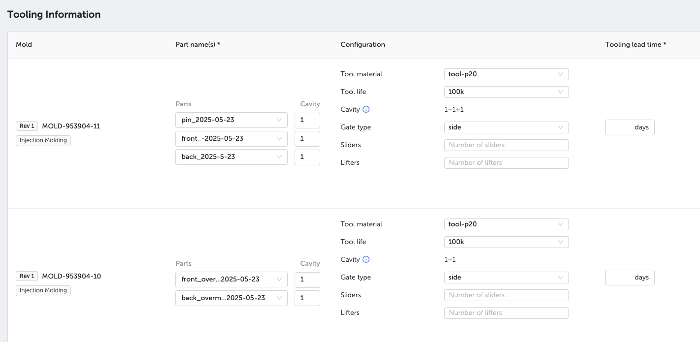
For our phone stand tool, we went with a P20 steel mold base with 100K shot life. The configuration was a 1+1+1 family tool (with 3 unique cavities) for the “front”, “back”, and “pin” parts, as well as a 1+1 tool for the TPU overmold parts.
This was a practical solution because the largest parts molded with PC/ABS were unique yet quite similar. However, after molding these parts, the 3-cavity tool had to be “washed” to remove excess material from gates and runners before injecting with glass-filled nylon for the smaller pin part. Cavities can be plugged, or closed off as necessary.
Every design choice impacts tooling cost, cycle time, part quality, and mold life. Once CAD is complete and the steel arrives, physical tool fabrication begins.
Learn more about injection molding tooling by downloading our production process guide.
Tool Base Fabrication
Every injection mold starts as raw steel blocks—massive chunks of potential. The mold is built in two primary halves: the core and the cavity, which together define the part’s shape. The core is typically convex to define internal features, and the cavity is concave to define the external geometry.
After squaring and surfacing the steel, the blocks are prepped for detailed machining.
CNC Machining: Cutting the Tool Geometry
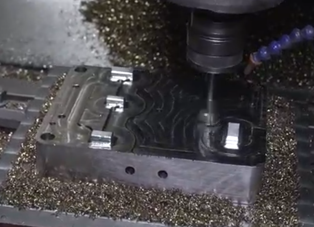
Once the steel is prepped, CNC milling is used to cut the majority of the tool’s geometry. High-speed machines carve out complex 3D shapes—bosses, ribs, shutoffs, and functional features—with tight tolerances and clean finishes.
Each half of the mold is machined separately, and alignment is absolutely critical. This is where precision matters: a micron-scale misalignment in the tool can result in flash, mismatch, or parts that simply don’t fit together.
Cosmetic surfaces are milled with careful attention to tool paths and surface finish, especially in areas that will be visible to users.
EDM: Electrical Discharge Machining
Electrical Discharge Machining (EDM) is used for intricate or inaccessible features that CNC tools can’t reach—sharp internal corners, thin vents, deep ribs, or fine logos.
EDM uses controlled electrical sparks to erode the steel. It’s a slower process than CNC, but essential for precision features that are often critical to functionality and appearance, such as:
- Sharp internal corners for snap fits
- Deep slots or vents
- Text or intricate logos
In my design, EDM was used to create the hinge pin snap fit geometry, the Fictiv logo, and the measurement markings, which required fine details.
Tool Components and Mold Architecture
Mold tools may start off as big blocks of steel—but become intricate assemblies made up of precise and often custom components that each serve a specific purpose in shaping, ejecting, and cooling the molded part.
Forming and Functional Inserts
- Cavity and Core Inserts
Interchangeable steel inserts that define part geometry, and are often replaceable for versioning or wear. - Core Pins
Used to form features like internal through-holes or bosses. These hardened pins are often modular or swappable. - Gate Inserts and Sprue Bushings
Guide the molten plastic into the cavity through the sprue and gate system. Gate inserts may be hot or cold runner compatible.
Motion Elements for Undercuts
- Sliders (Side Actions)
Move laterally to release undercuts or side details. Common in parts with holes or slots perpendicular to the parting line. - Lifters
Move at an angle to eject vertical undercuts, like locking tabs or ribs, without damaging the part. - Heel Blocks and Cam Pins
Guide slider motion, ensuring timing and structural integrity during mold open/close cycles.
Ejection and Support Components
- Ejector Pins
Push the cooled part out of the cavity. Placement and profile are critical to avoid part damage. - Retainer Plates and Support Pillars
Hold pins and inserts in position while managing stress and maintaining mold alignment. - Guide Pins and Bushings
Keep the mold halves perfectly aligned during each cycle. - Locating Rings
Ensure mold alignment with the injection molding machine’s nozzle and platen.
Cooling Channels and Thermal Control
Efficient cooling is just as important as the mold shape itself. Once the molten plastic fills the cavity, it must cool evenly and quickly to prevent defects and reduce cycle times.
- Integrated Cooling Channels
Internal passages are drilled or milled into the mold to circulate water or oil. These are typically optimized during mold design to reach key thermal zones near the part surface. - Baffles and Bubblers
Specialized cooling inserts that allow coolant to reach deep or tight areas that straight-line channels can’t access—especially important for tall cores or narrow features. - Thermal Considerations
Poor cooling can result in common defects, such as warpage and sink marks.
Tool Fitting and Assembly
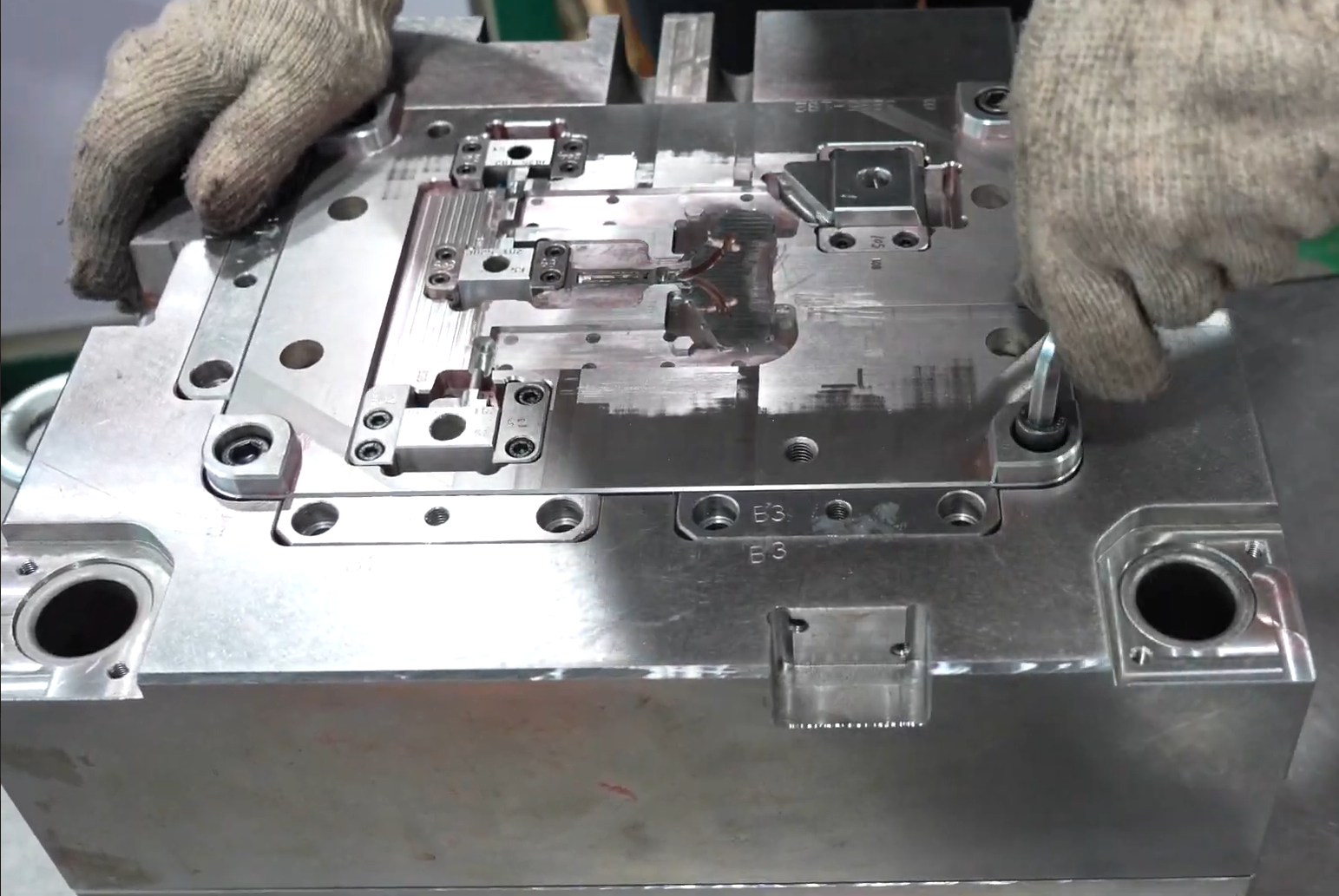
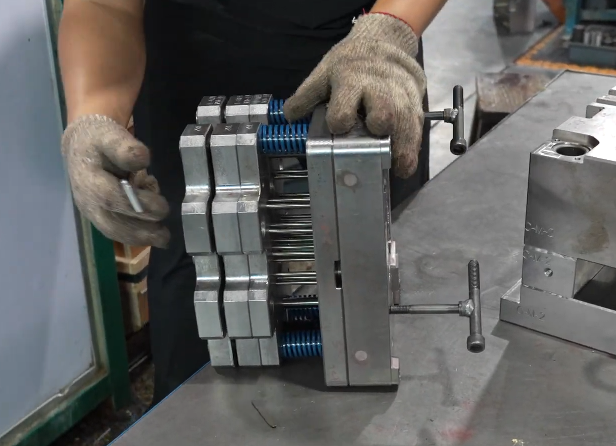
At this stage, toolmakers shift to benchwork and fitting.
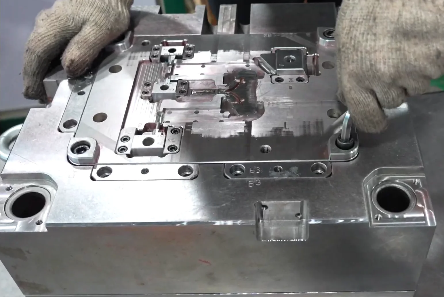
Core and cavity blocks are aligned. Sliders are installed and tested for motion. Ejector pins are checked for clean, even travel. Surfaces are polished, mating areas are deburred, and the tool is prepped for trial.
This is where craftsmanship and engineering come together, as hands-on tuning ensures that what works in CAD also works on the shop floor.
The CNC-Machined Blade: A Hybrid Manufacturing Feature
One standout element in this tooling project is the metal blade—a component that blends subtractive machining and injection molding by overmolding it as an insert.
The blade is CNC machined from aluminum and then anodized for corrosion resistance and a clean matte black finish. After anodizing, it’s placed into the injection mold cavity where the plastic overmold is formed directly around it. This requires tight tolerances and careful fixture design to ensure:
- Proper alignment of the blade within the mold
- No shifting during injection (which could cause uneven flash or part defects)
- Clean bonding between the blade and the plastic for structural integrity
Insert molding is an excellent solution for combining metal and plastic in one part, saving assembly time and ensuring repeatable alignment—especially for parts like this that serve both functional and aesthetic purposes.
Ready for T0: Tooling Complete
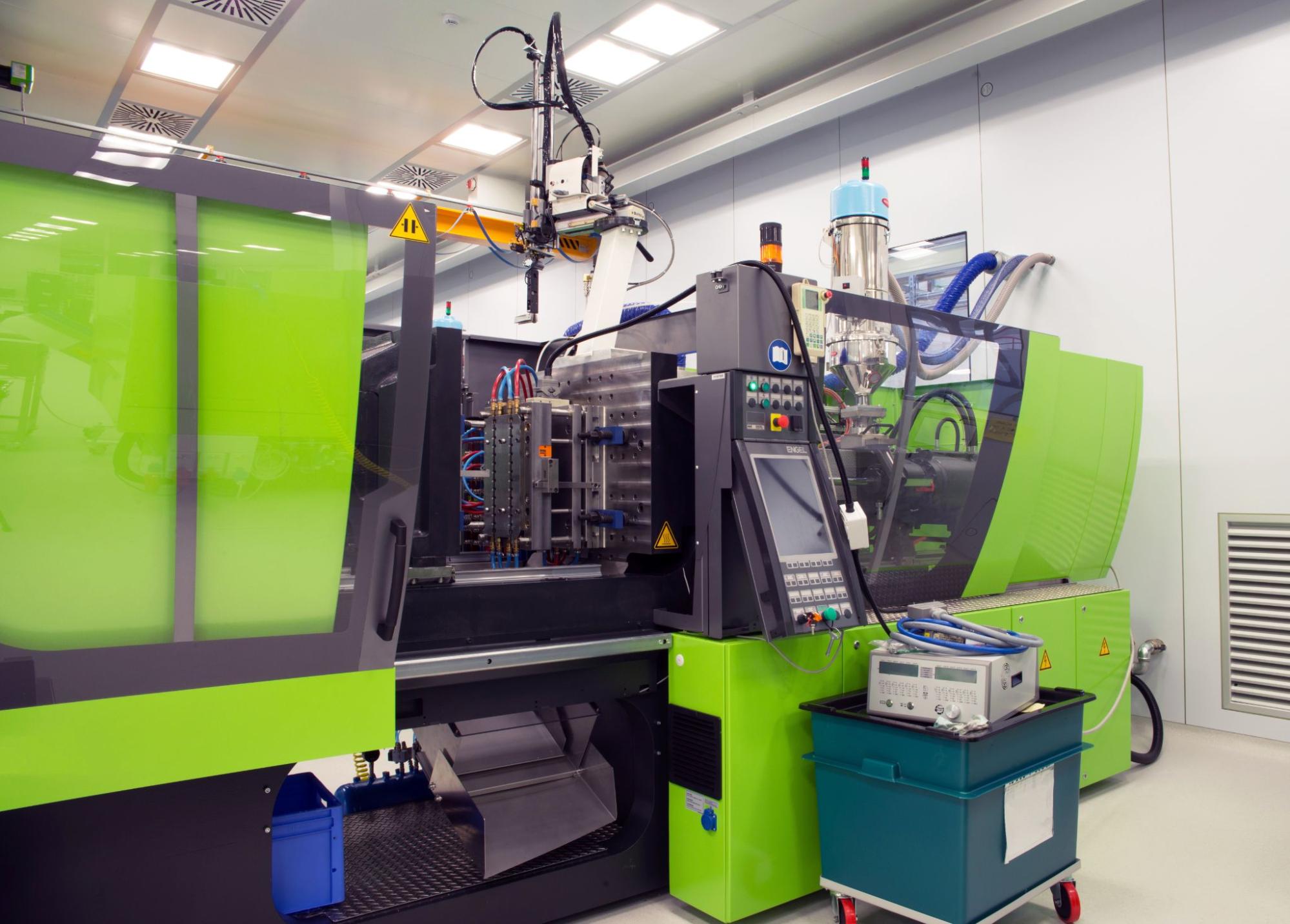
With all components assembled and validated, the mold is installed into an injection molding press for its first shots, known as T0.
This is the real test: molten plastic is injected into the mold for the first time. Engineers evaluate:
- Part fill and flow
- Flash or short shots
- Weld lines and sink
- Ejector pin marks
- Gate vestige and cosmetic quality
The goal of T0 is insight, not perfection. The data and visuals from these early parts will inform changes and refinements in the next step of the FictivMade process: sampling and iteration through T1 and beyond.
What’s Next in FictivMade
In the next chapter of FictivMade, we’ll walk through the tool validation process: covering mold trials from T0 through T3, including how we document and approve parts for production—and what happens when design revisions add complexity.
Stay tuned to see how trial shots become final parts.
How Fictiv Supports Tooling at Speed
Behind every molded part is a complex, high-precision tool—and behind every tool is a team of experts and a network built for speed.
At Fictiv, we manage tooling projects through our global network of vetted partners, ensuring high quality and fast injection molding lead times. Our Mold Library tracks tooling projects from design to delivery, giving engineers clear timelines, visual documentation, and full transparency.
Whether you need a single-cavity prototype mold or a high-volume multi-cavity production tool, Fictiv’s network can take you from CAD to T0 in record time—start your instant quote today.


