Time to read: 8 min
In injection molding, efficient tooling strategies are essential for maintaining quality while managing production costs. Among these strategies, family tooling stands out as a powerful method for manufacturing multiple components in a single molding cycle. Often used in scenarios where parts belong to the same assembly, family tooling enables cost-effective, streamlined production and faster time-to-market.
As manufacturers seek to optimize their processes and reduce waste, family tooling offers a compelling balance between productivity and affordability. This article will explore family tooling, its benefits, challenges, and key design considerations.

What Is Family Tooling?
Family tooling refers to a type of injection mold that contains multiple cavities, each designed to produce a different yet similar component in the same injection cycle, or shot. This approach differs from the use of single-cavity molds, which produce only one part per shot, and multi-cavity molds, which produce several identical parts per shot.
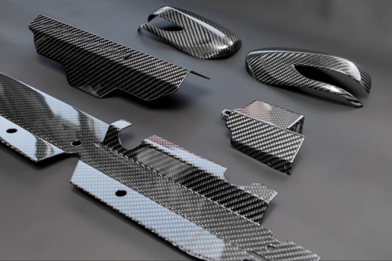
Family molding is particularly valuable for assemblies where multiple components are always used together—such as the top and bottom halves of a housing, or a frame and its cover. By integrating these parts into one mold, manufacturers can produce complete assemblies in less time and at a lower cost compared to if each part were molded separately.
Family Mold vs. Single-Cavity and Multi-Cavity Molds
| Tooling Type | Description | Parts per Cycle | Use Case |
| Single-Cavity Mold | One cavity per part | One component type | Prototyping or low-volume production |
| Multi-Cavity Mold | Multiple cavities of the same part type | Multiple identical parts | High-volume manufacturing |
| Family Mold (Tooling) | Multiple cavities for multiple part types | Multiple unique parts | Assemblies, kits, and related or similar components |
How Does Family Tooling Work?
Injection Molding Cycle
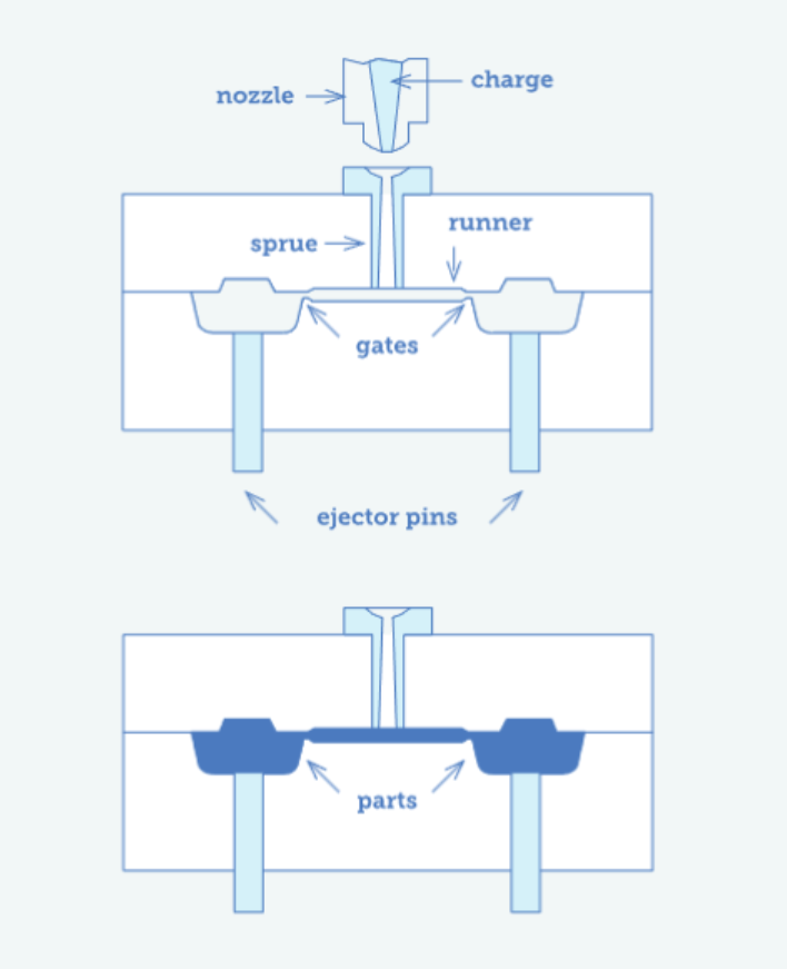
- Once the mold is closed and preheated, molten thermoplastic is injected into the mold. The plastic travels through the main sprue into the runner system and then into each cavity.
- Next, pressure is held to ensure that each cavity is packed as the pressure forces additional liquid material into the mold to compensate for shrinkage as the material cools.
- After packing is complete, the pressure is relieved, but the mold remains closed as the plastic solidifies and cools. After cooling in the mold, the parts are ejected and proceed to the next stage of the production process.
- Because the parts may differ in thickness and volume, engineers must optimize the cycle time based on the slowest cooling part. Otherwise, premature ejection can damage parts or leave them warped.
Mold Design and Layout
Engineers begin by designing the mold to house the cavities for the multiple component types to be contained within a single mold base. Each cavity is precision-machined to match a different required part geometry. Key layout considerations include:
- Part placement to balance the mold’s mechanical and thermal performance
- Runner length and gate positioning to ensure that each mold cavity fills simultaneously and completely
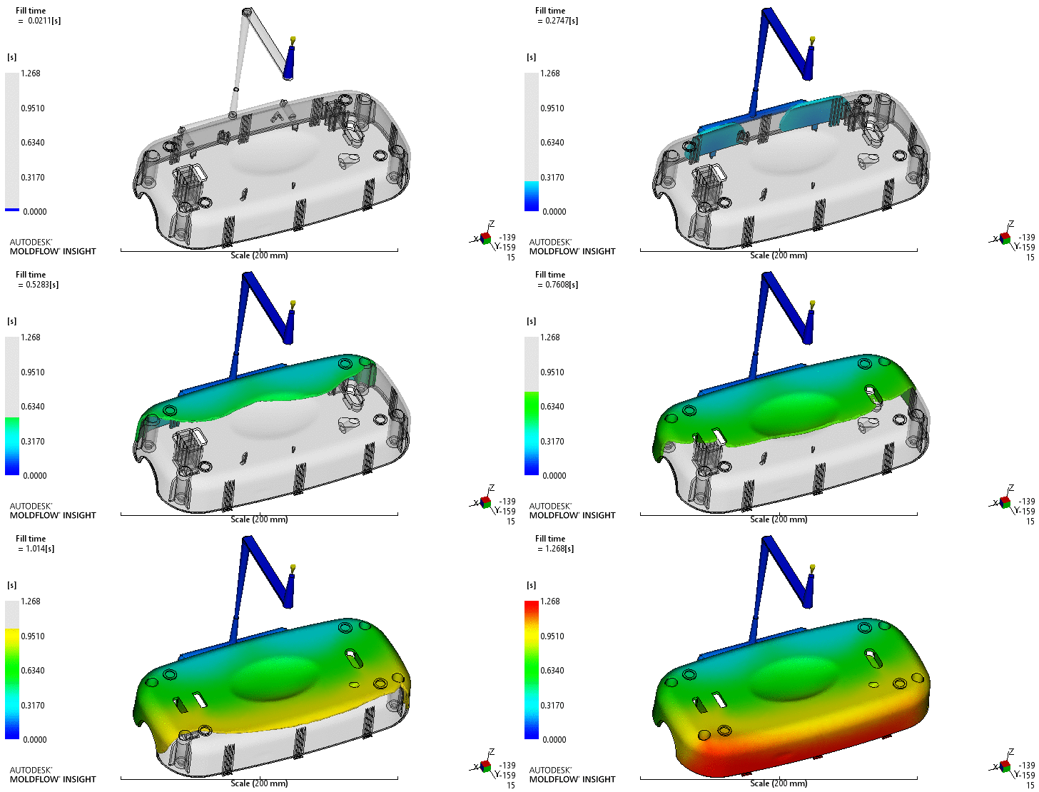
Because the part cavities differ in size, volume, and shape, engineers must account for these variations—a challenge that requires the use of simulation tools (e.g., mold flow analysis) and meticulous design.
Balancing Material Flow
Inconsistent fill across cavities can result in some parts being fully formed while others are incompletely filled, warped, or have excessive flash. To ensure even material distribution, mold designers often use mold flow simulation software to test different runner and gate placement strategies. Some key considerations for balancing material flow are:
- Runners must be designed to deliver equal pressure and flow to each cavity.
- Gate sizes might be adjusted based on each part’s volume.
- Flow restrictors or baffles may be used to slow the flow to smaller cavities.
If a large part and a small part are molded together, engineers may need to adjust runner paths or gate areas so that both parts fill at the same rate and pressure, reducing the risk of defects.
Benefits of Family Tooling
Family tooling is popular in many industries because it often aligns with lean manufacturing principles, speed-to-market goals, and cost-control strategies. Below are some benefits of family tooling.
Cost Efficiency
Investing in one mold that can produce several different parts for an assembly incurs significantly lower overall tooling costs compared to creating separate molds for each component.
Time Savings
With all parts molded in a single shot, production time is significantly reduced. This is particularly advantageous for components that will be assembled, as they exit the mold simultaneously and are ready for downstream processes.
Material Consistency
Because all parts come from the same shot of material, mechanical properties, color, and texture remain consistent across components. This is critical for quality and aesthetics.
Ideal for Assemblies
When producing kits or assemblies (such as a remote casing and button pad), family tooling helps ensure that all parts are dimensionally and visually consistent, which helps ensure assembly fit and aesthetic matching.
Waste Reduction
Fewer molds and optimized runner systems mean less scrap and more efficient use of resources. Additionally, depending on the type of plastic used, the solidified runner system material can be recycled by pelletizing it and mixing it with virgin material.
Limitations and Challenges of Family Tooling
While family tooling offers many advantages, it also introduces several engineering and process challenges. These limitations must be carefully considered during the design and planning phases.
Part Defects and Short Shots
Since the parts differ in size and shape, achieving balanced fill across cavities is more complex than with uniform multi-cavity molds. Unbalanced fill—whether caused by poor runner design, gate design, or unoptimized molding parameters—can lead to short shots, overpacking, or visual defects such as warping or sink marks.
Cooling and Shrinkage
Different part geometries may have varying cooling rates, which can result in inconsistent shrinkage and dimensional discrepancies between parts molded simultaneously. To counter this, cavities may have their own independent cooling channels, or cycle times may be optimized based on the slowest cooling part.
When Family Tooling is Not Viable
For large or highly complex parts that have extremely tight tolerances, or when parts vary greatly in volume, family tooling may become impractical or result in too many compromises in visual and performance quality or cycle time. In this case, manufacturers may opt for single-cavity tooling.
Key Design Considerations for Family Tooling
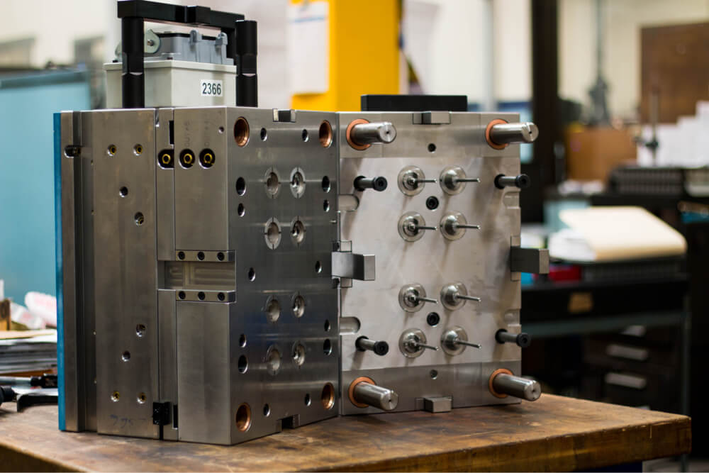
Successful implementation of family tooling depends heavily on careful design decisions. Molding multiple different parts within a single cycle requires the mold design to balance functionality, manufacturability, and part performance—all while minimizing risks of defects and inefficiencies. Here are the most critical factors to consider:
Part Similarity
The more similar the parts are in size, wall thickness, and material volume, the easier it is to balance the fill and cooling rate. Significant differences can cause one part to fill too quickly (leading to overpacking) while another fills too slowly (leading to short shots).
Wall Thickness Uniformity
Maintaining uniform wall thickness across all parts in the mold helps minimize uneven cooling, internal stresses, and cosmetic defects. Drastic differences in thickness between parts will result in inconsistent cooling rates and higher chances of warping or sink marks. Use gradual transitions where wall thickness must change and optimize gate and runner design to compensate for volume and thickness differences.
Tolerance Stack-Up
Family tooling is often used for assemblies where parts must fit together or interact with each other. In these cases, you must account for tolerance stack-up—the cumulative effect of dimensional variations between mating parts. It’s critical to design parts with compatible tolerances that allow flexibility and account for potential variation due to cooling, shrinkage, or ejection stress.
Ejection and Venting
Both ejection and venting play a crucial role in the quality of a family-molded product. When it comes to part ejection, different part geometries may require unique ejection mechanisms. For instance, flat parts may need ejector plates, while complex forms may require pins or sleeves.
Venting ensures that gas in the mold at the start of the injection cycle has an escape path so that it does not become entrained in the liquid plastic and produce burn marks. Both ejection and venting systems must be properly designed to ensure product quality.
Applications and Industry Examples of Family Tooling
Family tooling is utilized in various industries that require the efficient, consistent, and cost-effective injection molding of related parts.
Below are some common industrial applications of family tooling injection molding and how specific industries benefit from the technique:
Consumer Electronics
Many electronic assemblies, such as remote controllers, speaker housings, and PCB assembly components, require multiple plastic components to be produced with aesthetic and dimensional consistency. Family tooling enables manufacturers to mold both front and back housing shells, along with buttons or gaskets, all in a single cycle. This approach ensures color match, material uniformity, and perfect fit—essential for consumer-facing products like remote controls, headphones, or routers.
Medical Devices
Medical products often consist of several interrelated plastic parts, and the industry demands high precision, cleanliness, and consistency. Family tooling helps meet these requirements by producing parts from the same mold while reducing costs in regulatory environments where validation and compliance are time-consuming and expensive. Medical devices, such as housings for diagnostic kits or handheld devices, instrument handles, and more, are often manufactured using a family tooling approach.
Automotive
Automakers require millions of injection-molded parts on tight timelines, meeting strict quality standards. Clips, brackets, and interior trim parts are often molded together and used in the same sub-assembly.
Family Tooling vs. Multi-Cavity Tooling
Family tooling and multi-cavity tooling are both used to increase injection molding efficiency, but they serve fundamentally different purposes. Understanding when to use each type is key to selecting the right tooling strategy for your manufacturing goals.
Family Tooling and Multi-Cavity Tooling Comparison
| Feature | Family Tooling | Multi-Cavity Tooling |
| Parts per cycle | Multiple different parts | Multiple identical parts |
| Best for | Assemblies, kits, low-to-medium volumes | High-volume production of a single part |
| Tooling cost | Potentially higher upfront cost due to added complexity, but lower than multiple tools | Higher upfront cost than single-cavity, increased cost efficiency over time |
| Cycle time utilization | May be less efficient due to varied part geometries | Optimized for identical part geometry |
| Material consistency | Moderate – same material across parts, but geometry may affect flow and cooling | High across units (identical parts) |
| Complexity of mold design | Higher due to unbalanced flow, ejection needs | Moderate; symmetrical design simplifies flow |
| Risk of defects | Higher if parts differ significantly in size or shape | Lower as conditions are optimized per part |
| Flexibility for changes | Can accommodate multiple designs, but any change may affect all parts | A design change must be made across all cavities in production |
| Maintenance/Repair | May impact all parts of the tool | Only one part type affected |
Is Family Tooling Right for Your Injection Molding Project?
Family tooling isn’t universally applicable. While it offers compelling advantages, it also comes with design and process limitations. To determine whether it’s the right choice for your project, consider the following decision-making criteria:
Volume Expectations
Low-to-mid volumes are ideal for family tooling, where the cost of creating multiple molds can’t be justified. Having different cavities enables more flexibility in design iteration with prototype tooling. For high-volume production, multi-cavity or dedicated tooling becomes more cost-effective and easier to scale.
Complexity and Symmetry of Parts
Consider whether parts are similar in size and complexity. Highly asymmetrical parts can be difficult to fill uniformly, leading to process imbalances, short shots, or overpacking.
Tolerance Requirements
For parts of an assembly, consider how tight tolerances must be. Tight-tolerance assemblies may require additional design safeguards or separate molds if part performance is critical.
Material Type and Aesthetics
Consider the importance of visual consistency in the parts. Family tooling is a good fit when uniformity of appearance and consistency of performance across components are essential.
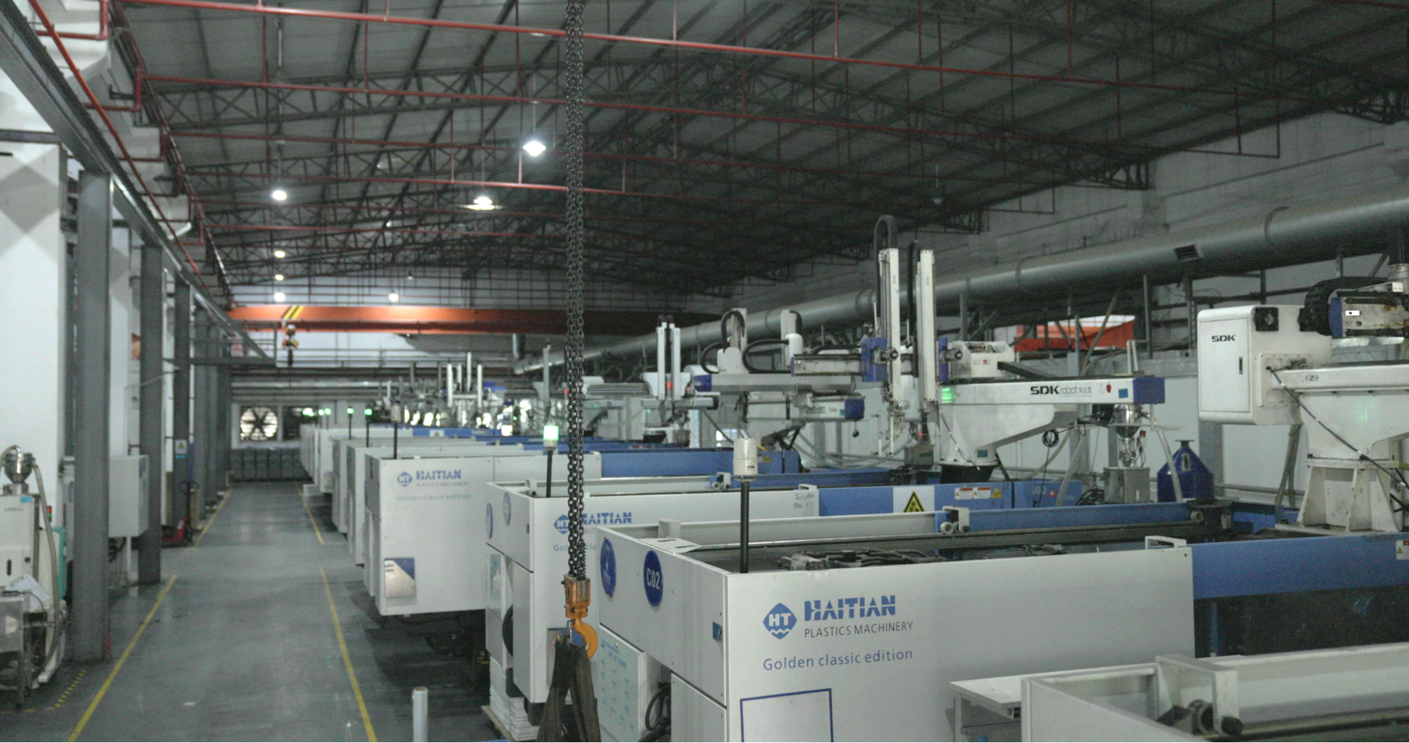
Fictiv for Family Tool Injection Molding
Got a complex injection molding project? We’re here to help you optimize mold layout, part compatibility, and production efficiency from day one.
Whether you’re producing low- to mid-volume assemblies or accelerating a product launch, our engineering expertise and network of vetted partners ensure you don’t have to choose between quality, speed, and cost efficiency.
Ready to simplify your tooling strategy? Get started with a quote today.


