Time to read: 6 min
Draft angle injection molding is about applying an angle or taper to the vertical faces of injection molded parts. Draft is measured in degrees and promotes smoother part ejections, decreased tooling wear, and shorter cooling times. The benefits of proper draft include fewer defects, faster cycles, and lower costs.
Typically, designers apply draft angles of 1.5° to 2° degrees to injection molded parts at mold depths up to 2 inches. Applying a slight taper like this might seem simple enough, but you can’t add the same amount of draft to every part – and minimum and maximum draft angles for injection molding can vary considerably.
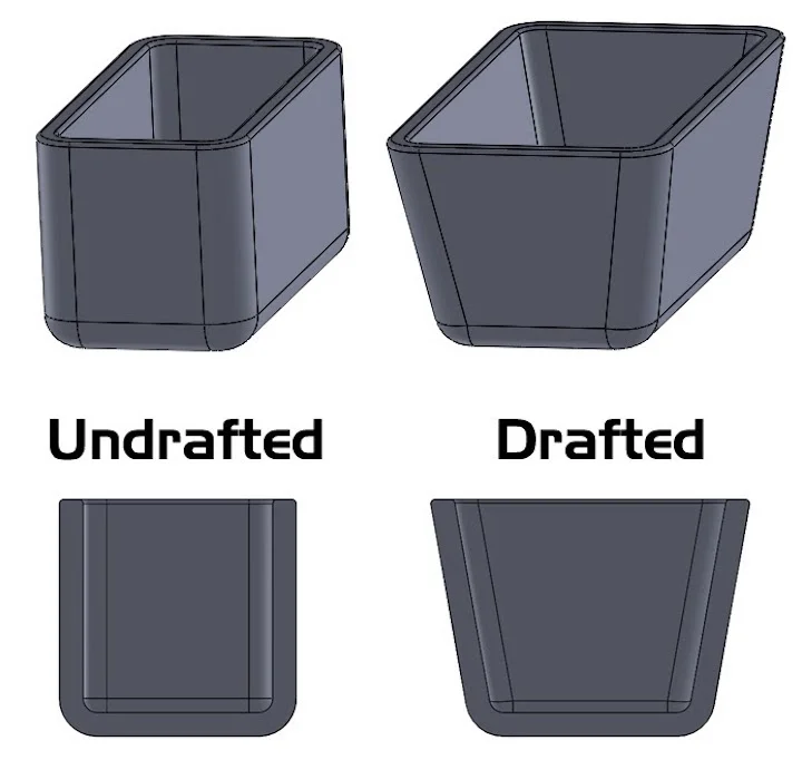
There are many reasons for this. For starters, draft varies by injection molding material or resin. Since there are hundreds of different resins to select, including both commodity plastics and specialty materials, it’s easy to see why there isn’t a standard draft angle for injection molding.
Part features, surface finish, injection molding standards, draft direction, and mold design also determine how much draft to apply. Some draft is better than no draft but remember that draft angles in injection molding aren’t optional – at least if you want parts that are free of scratches and cost-effective to produce.
What happens to injection molded parts without enough draft? Sometimes, a mold’s ejector pins mar the part’s finish or geometry. Inadequate draft can also cause mold wear because of the rubbing, and resulting friction, which happens when there’s not enough room for an injection molded part to clear the mold.
This article explains how to avoid these problems so that you can use draft angle injection molding to get complex parts at amazing speeds. Keep reading to learn more and download this free e-book for additional design guidelines such as wall thickness, transitions, and corners.
Download the Injection Molding Design Guide
Draft and Injection Molding Materials
When a thermoplastic resin cools inside an injection mold, the polymer shrinks by a certain percentage. This reduction in size creates surface tension between the walls of the plastic part and the walls of the injection mold. In turn, this tension can prevent parts from sliding smoothly as they are ejected.
Because different thermoplastics cool and shrink at different rates, designers need to account for the thermal behavior of the resins they want to use. As a rule, plastics that shrink by a larger percentage require a greater draft angle. In addition to the shrink rate, there are other properties to consider.
Strong, brittle, and abrasive materials such as glass-filled plastics require larger draft angles than soft, ductile, or self-lubricating resins like nylon or polyethylene (PE). In the case of nylon, draft may not be required, but it’s still recommended.
The table below contains draft angles for some commonly used injection molding materials.
| Material | Minimum Draft | Recommended Draft |
| Nylon | 0° | 1° |
| Polyethylene (PE) | 0.5° | 1.5° |
| Polyvinyl Chloride (PVC) | 0.5° | 1.5° |
| Polypropylene (PP) | 1° | 2° |
| Polycarbonate (PC) | 1.5° | 2° |
Draft and Part Features
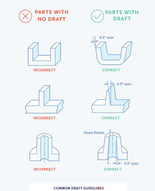
The walls of your injection molded part aren’t the only features that require a draft angle or taper. All vertical part features, including ribs and bosses, require an adequate draft. The depth of these features and their minimum thickness determine the specific angle to apply. The table below explains.
| Feature Depth | Minimum Thickness/Draft | |||
| 0.25 in. | 0.040 in./0.5° | |||
| 0.5 in. | 0.040 in./1° | 0.060 in. /0.5° | ||
| 0.75 in. | 0.040 in. /2° | 0.060 in. /1° | 0.080 in. /0.5° | |
| 1 in. | 0.060 in. /2° | 0.080 in. /1° | 0.100 in. /0.5° | |
| 1.5 in. | 0.080 in. /2° | 0.100 in. /1° | ||
| 2 in. | 0.100 in. /2° | |||
Draft and Surface Finishes
Plastic injection molding can apply a specific polish or texture to your parts during the molding process. When your mold is made, the desired finish is applied to the tool. Then, during injection molding, this finish is transferred to the surface of your parts.
Parts with smoother finishes require less draft because they’re easier to eject and less prone to dragging along mold surfaces. By contrast, finishes with heavier textures require greater draft. Typically, part designers add 1.5° of draft per 0.001” or 0.025 mm of textured depth.
Here are some general injection molding draft angle guidelines based on surface finish and texture.
- Smooth Finish: 1 to 2 degrees (typical)
- Light Texture: 3 degrees
- Heavy Texture: 5 degrees or more
For textured surfaces on plastic parts, a heavier draft is essential for avoiding drag marks. Parts with a leathery or snakeskin-like finish may require significantly greater draft (10° or more) because texturing is produced with a series of small undercuts that complicate part ejection.

Draft and Injection Molding Standards
The standards for surface finishes are defined by trade associations and companies. The Society of the Plastics Industry (SPI) and the Society of German Engineers / Verein Deutscher Ingenieure (VDI) are two of these trade associations. Mold-Tech (MT) and Yick Sang (YS) are companies with their own standards.
Within each surface finish standard, there are hundreds of different options. For identification purposes, each finish has a callout that consists of the organizational acronym followed by letters or numbers. For example, MT-11010 is a Mold-Tech designation for a light mold texture.
The surface finish chart below lists the required draft for the most common SPI, VDI, MT, and YS finishes. To achieve a mirror finish, electro-discharge machining (EDM) is used instead of CNC machining or hand polishing.
| SPI Standard | Draft | Mold Tech Texture | Draft |
| A-1 | 2° | MT-11000 | 1° |
| A-2 | 2° | MT-11010 | 1.5° |
| A-3 | 2° | MT-11020 | 2.5° |
| B-1 | 1° | MT-11030 | 3° |
| B-2 | 1° | VDI Texture | |
| B-3 | 1° | VDI-18 | 1° |
| C-1 | 1° | VDI-24 | 1.5° |
| C-2 | 0.5° | VDI-33 | 3.0° |
| C-3 | 0.5° | YS Texture | |
| D-1 | 1° | YS20001 | 1° |
| D-2 | 2° | YS20005 | 3° |
| D-3 | 3° | Mirror EDM | 3° |
Draft Direction and Injection Mold Design
When you apply draft to injection molded parts, make sure to do so based on the mold’s draw: the direction in which the core and cavity separate. Otherwise, your plastic part may not stay in, or stick to, the half of the mold that contains the ejector system.
It’s also essential to account for part features like holes. For example, in the case of a rectangular part with four through-holes, drafting the holes toward the cavity could cause parts to stick to the cavity instead of the core. A better approach would be to draft the holes toward the core where the ejector system is located.
Parting line location can also affect draft. If a mold’s parting line is stepped, then a special surface called a shut-off is needed so that there isn’t a gap between the two halves of the mold when they’re closed. Typically, part designers apply a 5 to 7 degree draft angle to avoid this problem.
If the parting line is in the middle of your part, such as with a solid cylinder, incorporate draft on both ends of the part. That’s because your part requires not one but two mold release actions, both of which require enough draft.
Your mold’s materials of construction also affect draft decisions. For example, aluminum molds are less precise than steel molds. They’re also machined with different tools called mills. Consequently, aluminum molds may require more generous draft angles for dimensional deviations.
To achieve some finishes, steel molds are needed. For example, Fictiv recommends a hardened steel mold to achieve SPI levels A-1, A-2, or A-3. Hardened steel withstands potential ripples, sags, and crests from machining and polishes better than molds from aluminum or softer steels.
Draft Angle Injection Molding from Fictiv
As you’ve learned from this article, it’s not so simple to determine which draft angle to use with injection molded parts. There are many factors to consider, including the thermoplastic resin, part features, surface finish, injection molding standards, draft direction, and mold design. You’ll also need a skilled partner.
Generally, designers apply draft angles of 1.5° to 2° degrees to injection molded parts at mold depths up to 2 inches. It’s also best to determine the amount of draft you need early in the design process. That way, you won’t have to redesign your parts so that they’re easier and less expensive to mold.
Fictiv provides design for manufacturing (DFM) feedback along with your request for a quote. Getting started is as easy as creating a free account and uploading your part drawing. With help from our engineering experts, you can avoid pitfalls such as inadequate or missing draft.
Working with us also means getting complex parts at amazing speeds – even with finer finishes. For low-volume injection molding between 100 and 100,000 parts, Fictiv offers molds made from P20 and NAK80 steels instead of aluminum. Typically, these steel tools are ready for parts production in about two weeks.
For higher-volume production, or for especially demanding finishes like mirror EDM, we offer hardened steel molds instead. These longer-wearing tools support even tighter tolerances, and you’ll get expert DFM assistance along with access to our carefully vetted network of injection molders.
If you’re looking for the right angle for your next injection molding project, choose Fictiv.


