Time to read: 7 min
Hinges are everywhere—from your front door to the laptop on your desk. Many products need to be able to rotate reliably with positional accuracy. But designing hinges can be complex, and there are several ways to go about it. A simple press-in pin can work great for a prototype, but may not hold up in production parts.
At a glance, a hinge may seem as simple as allowing a pin to rotate inside a bore, but the interplay of tolerances, clearances, material flexibility, and tool design creates a delicate balance between free motion and structural integrity. My experience designing the multi-tool phone stand highlights some of these challenges and solutions developed in collaboration with our manufacturing partner.
Initial Hinge Concepts
When looking at a more robust solution for production, I considered pros and cons of the following options:
- Press-fit pin
Pros: Simple design
Cons: Can come loose with use and wear
- Off-the-shelf metal hinge
Pros: Save design time
Cons: Cost
- Concentric snap fit
Pros: Simple assembly, fewer parts
Cons: Can come apart
- Longitudinal snap-fit pin
Pros: Proven from past products
Cons: Challenging to tune the design
- Heat-staked or ultrasonic-welded pin
Pros: Solid connection
Cons: Extra process/cost that requires tuning
Pros: Simple solution, fewer parts
Cons: Not as robust or applicable
After evaluating these possible hinge solutions, I opted to go with the option that I felt was the most feasible and reliable within the timeline. Read on to see how I experimented with a press-fit pin in prototypes to prove out the concept, with the plan to use a longitudinal plastic snap-fit pin in production.
Splitting the Master Part Into Hinge Components
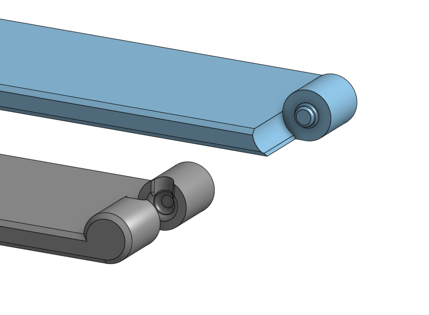
One of the first challenges in hinge development is determining how to split the master part in CAD for optimal functionality, molding, and assembly. For my hinge design, this meant separating the pin from the mating parts of the bore so that each part can be tooled and molded without undercuts or complex slides.
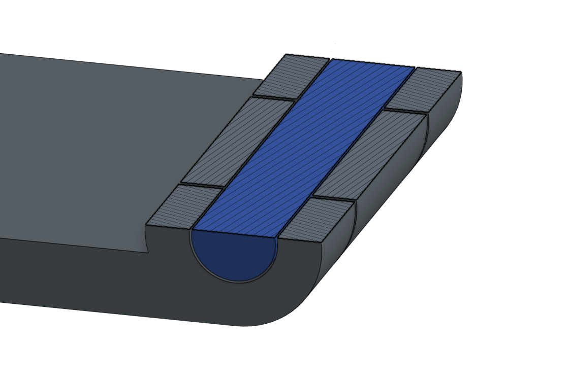
Taking a look at the design, you can see how I split the three parts to confine them along the horizontal axis, while allowing rotation about that axis.
Overall Hinge Diameter
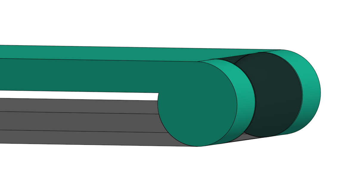
I started this model with a middle plane to mirror the main parts with symmetry, which would also act as the midpoint of the hinge. I used a circular sketch tangent to the front face, with the center point coincident with this plane, as a driving component for this section. Adjusting its diameter to account for the wall thickness necessary also drove the overall thickness of the collapsed assembly.
Inner and Outer Hinge Section
I then had to extrude the overall hinge section and split the main front and back parts so that the back included an inner cylinder and the front included outer bosses to constrain it. Depending on your modeling preference, this can be done with offset surfaces or sketch-driven extrusions. I included offsets from the driving sketches to create the necessary clearance.
Hinge Pin Integration
The boss for the hinge has been split, but I needed to integrate the bore to hold the pin in place. I did this by coring out both parts with another offset circular extruded cut. Then I added two more recessed cuts for the head of the pin and the snap feature on the other side. This allowed me a nice slot to model in the pin itself.
Steel-Safe Strategy
Because removing tool steel to tighten a hinge fit is easier than enlarging a bore by adding steel, the clearance is often designed to be oversized at first. This allows room for adjustments to be made without requiring costly tool rework. This is the approach I took which led to some necessary tuning I will cover later in this article.
Prototyping the Hinge With 3D Printing
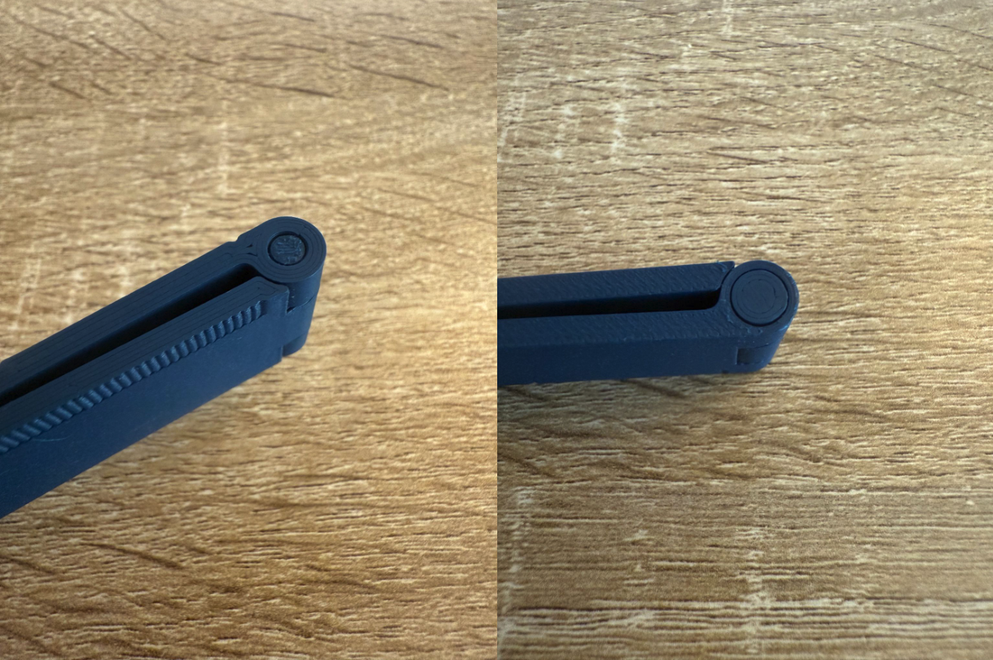
To test out the concept, I started with 3D printing. I designed a simple, flanged pin with a slight press fit that was just enough to hold it in place. This was relatively straightforward to accomplish, thanks to a quick tolerance stack analysis based on the resolution of the 3D-printed parts.
Tip: With similar designs, it’s essential to consider the type of fit you are aiming for and design it accordingly. Especially with metal parts—you will have slightly less flexibility than with plastic.
Constraining Degrees of Hinge Rotation
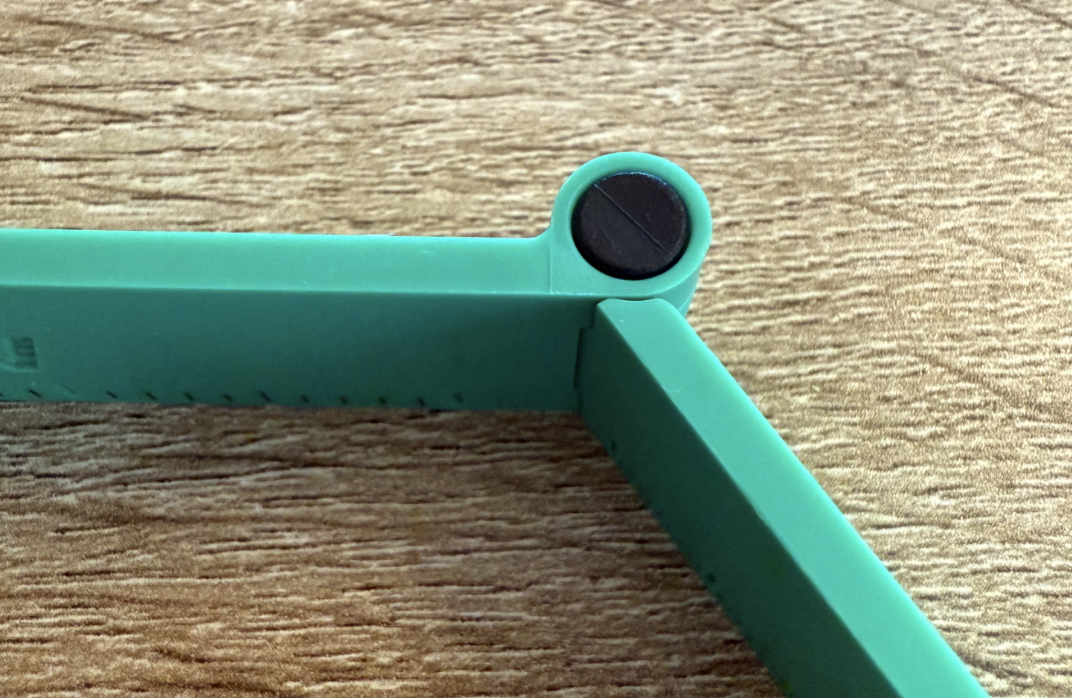
Another factor in hinge design is how much you want it to be able to rotate. In many cases, you will have outside physical constraints, like a door frame or wall stopper. In other cases, you may want to consider designing in a hard stop to your parts to prevent over-rotation or only allow certain angles of rotation.
For my design, I considered a hard stop feature that would limit rotation to a certain angle for the largest device it may hold. To simplify the design, I decided not to include this feature, so the user can determine the angle that works best for their device.
Hinge Design for Manufacturing (DFM)
A hinge should perform reliably and integrate aesthetically into the product, but it also needs to be designed to be manufacturable, repeatable, and cost-effective.
Draft Angles
Applying draft to both pins and bores ensures parts release cleanly from the mold. Too little draft increases risk of the parts sticking in the tool, and too much draft compromises engagement of these parts that need to fit together solidly. Therefore, I had to find a balance in this design.
Coring and Flexibility
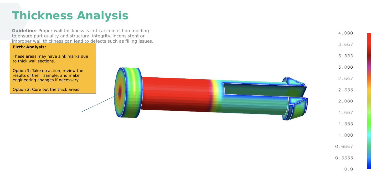
Snap-fit pins often require cored-out sections to provide flexibility during assembly and reduce the risk of sink in thicker sections. However, too much coring reduces rigidity and leads to premature loosening, as I discovered with my initial design.
Material Considerations
The stiffness and creep resistance of the chosen resin will determine long-term hinge performance. Softer plastics may require tighter fits, while stiff engineering resins need more clearance to avoid cracking.
Also, with rotating parts that are in contact, you want to pay attention to the coefficient of friction between them. Using the same material can create a squeaking sound as the parts begin to rub against each other and wear. I started with POM for the pin, which has great lubricity. For additional stiffness, we made a change to glass-filled nylon, which also has good lubricity but higher tensile strength. I used PC/ABS for the mating parts around it.
For more insight on material considerations, check out our Materials.AI tool and guide to choosing the right material for your injection molding project.
Parting Lines
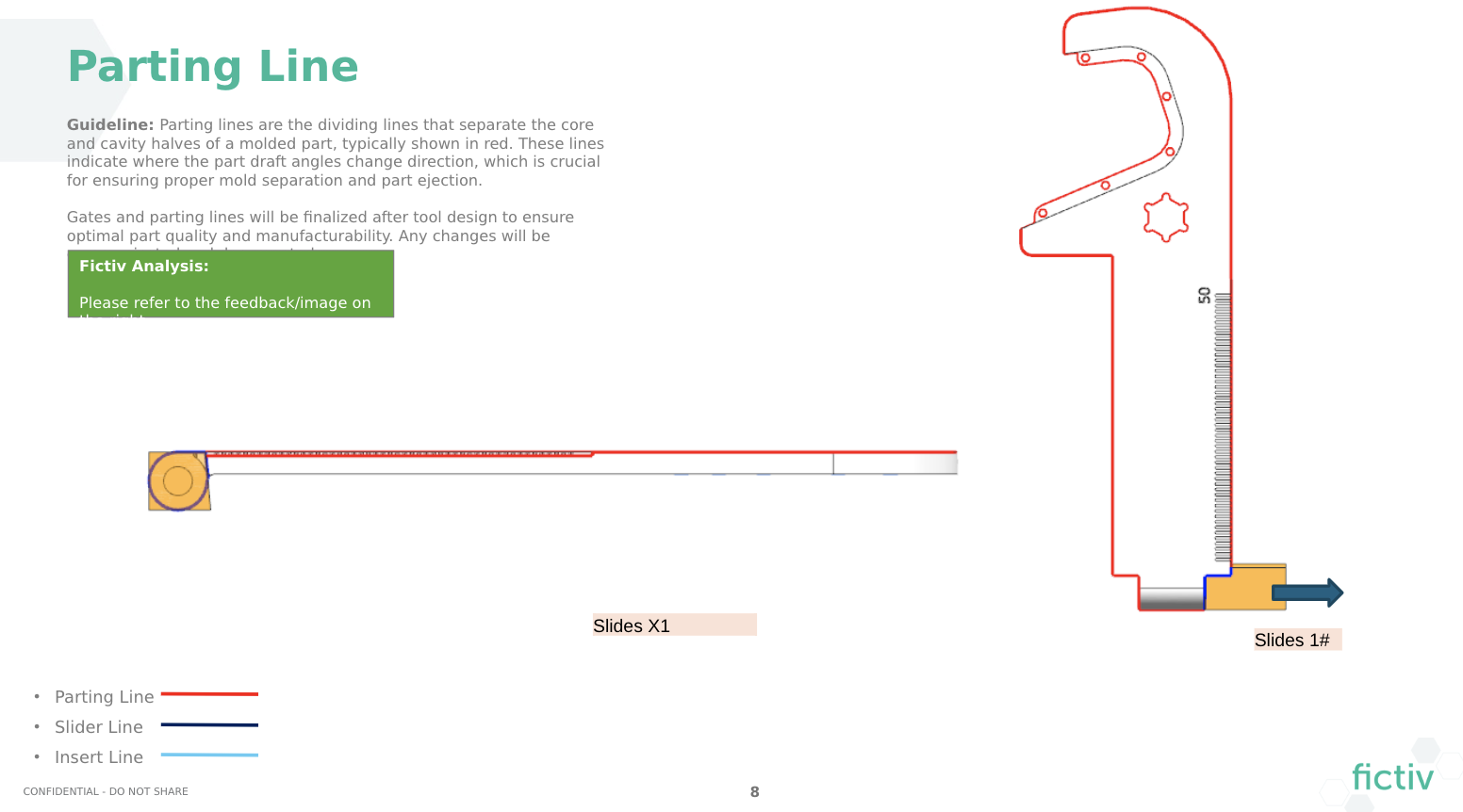
In the design, I also had to consider the parting lines and draft, which affected the fit and clearance. Because the hole for the pin had to be pulled on a slide (in a perpendicular direction to the mold core and cavity), there had to be a break in the draft at the parting line.
Hinge Tolerances and Clearance
Tolerance stack-ups and clearances are critical in hinge design, and can be a silent killer of hinge performance. In my design, I intentionally oversized the hinge bore to ensure that, across worst-case variation, the parts would still assemble without binding. This approach is conservative but often safer in injection molding.
Clearance First, Tightening Later: Starting loose allows for steel-safe tool changes to tighten the fit. This is preferable to designing too tightly, which can result in scrapped tools or costly modifications.
Perceived Quality vs. Functional Fit: A hinge that rotates freely but rattles or feels loose undermines user confidence. A balance between engineering tolerance and human perception is essential.
Modifications and Iterations for Hinge Looseness
When the T1 samples arrived, the hinge rotated and the pin could be easily assembled, but the fit was too loose. The pin could be flexed open and even disassembled without excessive force. Functionality was not up to par, and the product quality felt compromised.
Working with Alex Fu, TPM at our manufacturing partner in China, we reviewed options:
- Tool Modification: Removing steel to add plastic material on the pin and back components to close the clearance gap between mating parts.
- Pin Redesign: Adding material for structural reinforcement to the snap feature to reduce flex. This had to be done strategically to add rigidity in consideration of moldability and defect concerns such as sink.
- Material Adjustment: Considering a resin with slightly higher stiffness for better retention. I did some calculations and FEA for the snap force, and we ended up going with glass-filled nylon as the new
These iterative refinements produced a hinge that not only functioned as intended but also conveyed a sense of durability and quality in the assembled product. This case shows the importance of anticipating adjustments and designing hinge features with modification paths in mind.
Let’s take a look at the hinge cross-section in the CAD snapshot below, showing the final clearances.
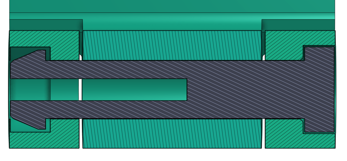
Cross section of hinge assembly in CAD
Key Takeaways for Hinge Designers
- Plan for Steel-Safe Modifications: It’s safer to leave room to tighten fits after initial mold trials.
- Balance Flexibility and Rigidity: Snap features need compliance, but not at the expense of stability and perceived quality.
- Design for Perception as Well as Function: A hinge that feels tight and strong, but also rotates smoothly elevates product quality.
- Collaborate Closely With Manufacturing Partners: On-the-ground feedback from your MP is invaluable for rapid iteration and issue resolution.
Want to test out your hinge design? Fictiv offers rapid prototyping and production services, including 3D printing, CNC machining, urethane casting, and injection molding.
Start your free quote today.


