

Time to read: 14 min
How to Transition from CNC Machining to Casting for Production Scale
Identifying the Right Parts for Casting
CNC vs. Casting: Fundamental Differences
Casting Process Selection
(DFM) Design Adjustments for Transitioning from CNC to Casting
Casting Design for Manufacturability (DFM) Considerations
Materials & Performance Considerations
Hybrid Strategy: Casting + CNC Finishing
Simulation & Validation
Tooling & Production Scaling
Cost & Volume Scaling Strategy
Common Pitfalls in Scaling Manufacturing
CNC to Casting DFM Checklist
CNC machining is a default choice for prototyping and early production, but it doesn’t scale efficiently. As volumes increase, many teams reach a point where machining cost, cycle time, and material waste become limiting factors.
Transitioning to casting can unlock significant cost savings and enable higher production throughput—but only if the part is redesigned correctly and the process is introduced at the right time.
This guide focuses on how to identify when a part is ready to move from CNC to casting, and how to execute that transition without introducing cost, quality, or tooling risks.

Identifying the Right Parts for Casting
Not every machined metal part is a good candidate for casting. To maximize return on investment (ROI), identify the parts in the bill of materials (BOM) where the geometry and volume justify the upfront cost of casting tooling.
CNC-Machined Components That Should Be Cast
Primary factors that justify casting metal parts include:
- High Annual Volume: The biggest driver of the machining vs. casting decision, Estimated Annual Usage/Volume (EAU) determines whether tooling costs can be amortized.
- Lead Time: CNC has shorter lead times upfront, but once tooling is complete, casting can produce parts at a higher throughput.
- Complex Geometry: Organic shapes, undercuts, internal cavities, and complex curves require extensive 3D surfacing on a CNC mill.
- 3+ Setups: If a machinist has to reposition the part multiple times to complete it, it’s a prime candidate for the geometric freedom casting provides.
- High Scrap (Material Waste): Parts hogged out of large billets, where the final volume represents a fraction of the starting block, generate significant scrap cost at scale.
- Weight and Wall Thickness: Thick-walled machined parts add unnecessary weight to the product. Casting allows the use of ribs and thin walls to maintain structural integrity while shedding mass.
Casting is typically worth evaluating when annual volumes exceed ~500 to 1,000 units, especially for parts with long CNC cycle times, multiple setups, or high material waste.

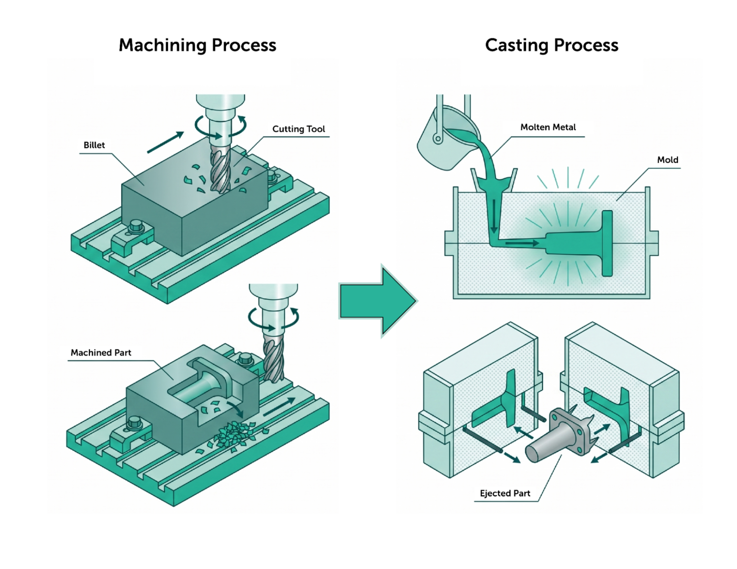
CNC vs. Casting: Fundamental Differences
To successfully transition a part from CNC to casting, engineers must reevaluate their design approach. Parts are no longer designed for CNC cutting tools. They’re designed for flowing liquid metal that solidifies in the mold.
Manufacturing Mindset Shift
A CNC mindset is subtractive: engineers may think in terms of tool reach, clearance, and machineability.
A casting mindset is formative: engineers may think in terms of flow, pressure, solidification, and cooling time.
Capability Comparison
Tolerances: CNC can easily hold tolerances of ±0.05 mm or tighter. Casting tolerances depend on the casting process, alloy, feature size, and tolerance grade. Use ISO 8062/CT grades as a starting point, or consult with your casting supplier on process capability; large sand castings may require mm-level tolerances, while die- or investment-cast features may be much tighter. For general dimensions, expect tolerances in the range of ±0.1 mm to ±0.5 mm.
Surface Finish: CNC produces smooth, machined finishes (typically 1.6 μm Ra or better). Castings have inherent surface roughness derived from the mold material—sand, ceramic, or steel. Both can be post-processed to change the finish.
Feature Limitations: When designing for CNC, engineers avoid deep pockets due to tool chatter. In casting, engineers embrace cored-out pockets to reduce mass. However, it’s important to replace sharp internal corners with generous fillets to prevent stress concentrations and tearing during cooling.

Casting Process Selection
Selecting the appropriate casting process depends on part geometry, material requirements, and production volume, and is a key factor in achieving cost and quality targets. Matching the part’s requirements to the appropriate process ensures you don’t overpay for tolerances you don’t need, or end up with a process that can’t meet volume demands.
Casting Process Comparison

Other specialized processes, such as centrifugal casting, are used for axisymmetric parts like tubes and rings, but are less common for general part geometries.
Achievable tolerances vary by process, part size, and geometry. In some cases, advanced sand casting processes can achieve comparable or better accuracy than permanent mold casting.
Matching the Casting Process to Your Part
To choose correctly, evaluate your part against three pillars:
- Volume vs. Complexity: High volume dictates die casting; high complexity with lower volume is ideal for investment casting.
- Tolerance Needs: If you need features with no post-machining, investment casting or die casting are the strongest options.
- Material Compatibility: Not all alloys can be cast in all processes. For example, high-melting-point steels are rarely die-cast due to thermal degradation of the dies. These are great candidates for investment casting.
Casting Process Snapshots
Sand Casting: Best for large structural components and low volumes. Sand casting requires large draft angles and generous tolerance allowances, but offers a significant reduction in raw material cost.

Investment Casting: Best for highly complex, intricate geometries, even with stainless steels or superalloys. Investment casting achieves near-CNC levels of detail without the tool-access limitations, provided heavy cross-sections are minimized to prevent shrinkage cavities.

Permanent Mold Casting (Gravity Casting): Offers lower turbulence and lower gas entrapment than conventional high-pressure die casting (HPDC), but mechanical properties depend on alloy, process control, heat treatment, porosity limits, and inspection requirements. HPDC can have more gas porosity, but structural, vacuum, and high-integrity die casting can be engineered for demanding parts.
- Gravity casting (most common)
- Vacuum, tilt-pout, low-pressure, and slush casting

Die Casting: Best for high-volume and thin-walled parts or enclosures across a broad range of industries, most commonly in aluminum or zinc. Die casting offers fast cycle times and a low piece price, but demands high upfront tooling costs.
- High-pressure die casting (HPDC)
- Low-pressure die casting (LPDC)

Use our CNC vs Die Casting Scorecard to help you compare and evaluate these process options for your parts
(DFM) Design Adjustments for Transitioning from CNC to Casting
Casting should not be treated as a direct replacement for CNC machining—parts must be redesigned for casting processes, including adjustments to wall thickness, draft, and geometry. Skipping design for manufacturability (DFM) is one of the most common causes of cost overruns and quality issues in casting programs.
Geometry Changes
Add Draft Angles: Cast parts require draft angles (typically 1° to 3°) to eject cleanly without damaging the mold or the part itself. Recommended draft angles depend on the part size and process:
- Sand casting: 2–5° draft
- Die casting: 0.5–2° draft
- Gravity/permanent mold casting: 1–3° draft
- Investment casting: 0–1° draft (wax removal dependent)
Increase Fillets and Radii: Sharp internal corners create stress concentrations where cracks form during cooling and restrict fluid flow. Replace them with generous radii.
Remove or Redesign Undercuts: Features that prevent the part from being pulled straight out of the mold require complex slides or cores. Eliminate them whenever possible to keep tool costs down.

Wall Thickness Optimization
In casting, thick sections are a liability because they cool more slowly than thin areas. This creates internal stress, warping, and shrinkage voids (porosity).
The location and severity of shrinkage-related defects are determined by part geometry and solidification direction, which is why uniform sections and proper feeding strategies are critical. Recommended wall thickness depends on process, alloy, part size, flow length, and structural requirements. Thin-wall die castings may be 1–3 mm thick, while sand/permanent mold steel, iron, or large aluminum castings often require thicker nominal sections.
To stiffen a part, add thin, drafted, intersecting ribs to provide structural rigidity without adding concentrated thermal mass by thickening walls. Rib thickness should be 50-70% of nominal wall thickness.
Part Consolidation
Part consolidation is one of the greatest ROI drivers when moving to casting. CNC parts are often limited by geometric reach, which forces engineers to design assemblies of multiple individual components. Casting removes this constraint, allowing engineers to combine multi-part welded or bolted assemblies into a single, highly complex cast component.
Critical Feature Redesign
Avoid casting precision or load-bearing threads. Cast the boss solid or with a pilot hole, and machine the threads as a secondary operation. For features that require tight tolerances (including bearing bores and sealing faces), add extra material (machining allowance so they can be CNC machined after casting.

Learn more about design considerations for casting in our die casting design guide.
Casting Design for Manufacturability (DFM) Considerations
Casting outcomes are largely governed by part geometry, which dictates how metal flows, solidifies, and feeds during the process. Small design changes early on can eliminate the need for complex tooling or process controls later. Good casting design requires a heavy dose of physics and metallurgy, which is where manufacturing simulation and expert DFM become critical.

Flow & Gating Considerations
Engineers should design the part so it can be gated, vented, fed, and ejected effectively; the foundry typically finalizes runner, gate, riser, vent, and overflow design. Designers must ensure that the metal can flow smoothly, without creating turbulence that traps air and creates defects. Part orientation within the mold affects filling and flow behavior, and should be considered in the design process.
Filling and Feeding
It’s important to distinguish between filling and feeding: filling is how molten metal enters the mold via the gating system, while feeding is the process of compensating for shrinkage during solidification by supplying extra molten metal via risers or pressure. Optimizing both may require tradeoffs in geometry and process design, as features that are easy to fill may be difficult to feed during solidification.
Shrinkage, Tolerances, & Allowances
Metal shrinks as it changes from a liquid to a solid, and shrinks further as it cools to room temperature. To account for this, provide a machining allowance (typically 1.5 mm to 3 mm) on any face that will require post-cast CNC machining to ensure the cutter doesn’t “air cut” or fail to fully clean up the cast surface.

Casting Defect Prevention
Casting defects are often driven by the interaction of part geometry, material behavior, and process conditions during filling and solidification. Understanding the root causes of common defects helps guide better design decisions and reduces the need for costly tooling or process changes.
- Warping: Caused by uneven cooling rates and thermal gradients across the part, leading to distortion. Prevented by designing uniform wall thicknesses and balancing mass distribution to promote even cooling.
- Misruns/Cold Shuts: Occur when molten metal solidifies before fully filling the mold or when two flow fronts fail to fuse properly. Prevented by avoiding overly thin walls, optimizing flow paths, and maintaining proper pouring temperature and speed.
- Shrinkage: Occurs when metal contracts during solidification without adequate feeding, creating internal voids or surface sinks. Prevented through proper riser design, directional solidification, and avoiding isolated thick sections.
- Inclusions: Caused by non-metallic contaminants (such as slag, oxides, or sand) becoming trapped in the casting. Controlled through clean melt practices, filtration, and minimizing turbulence during pouring, which can entrain surface oxides into the molten metal.
- Discontinuities: Includes cracks or separations formed due to thermal stress during solidification or cooling. Prevented by using uniform wall thicknesses, adding fillets, and designing to allow controlled contraction.
- Hot Tearing: Occurs when the casting is restrained during solidification and cannot contract freely, causing cracks at high temperatures. Prevented by using uniform wall thicknesses, adding fillets, and designing to allow for controlled contraction.

Why Casting Defects Are Difficult to Diagnose
Many casting defects—especially porosity—have overlapping causes, including shrinkage, gas evolution, and turbulence. Because of this, identifying the exact root cause often requires simulation or inspection rather than visual assessment alone.
Materials & Performance Considerations
Not every alloy can be transitioned from CNC to casting, as liquid-state material properties may not suit the casting process.
Machined aluminum parts are often made from 6061-T6 billet, which does not cast well. Instead, cast aluminum parts are often fabricated from casting alloys like A356 or A380, which contain silicon to improve fluidity.
Because castings have a dendritic, non-wrought grain structure (unlike the engineered, directional grain structure of rolled, extruded, or forged billet), cast parts may have lower tensile strength and ductility. If a direct material substitution causes a reduction in these mechanical properties, use the geometric freedom of casting to add structural ribs or slightly increase critical wall thicknesses.
Mold materials and binders can also influence casting quality, as reactions between the molten metal and the mold can introduce gases or contaminants that contribute to porosity.
Common Casting Materials
Casting processes use different alloys than CNC machining, optimized for flow, solidification, and defect resistance rather than machinability. Cast alloys are specifically formulated for fluidity and defect control, so direct equivalents to common CNC materials (e.g., 6061) are not always available.
Aluminum Alloys offer a good balance of strength, weight, and castability.
- A356, A357 (for sand/investment casting)
- ADC12, A380 (for die casting)
Steel and Iron are used for high strength, wear resistance, or cost-sensitive large parts.
- Carbon steel, stainless steel (for investment casting)
- Gray iron, ductile iron (for sand casting)
Zinc Alloys are excellent for high-volume die casting with fine detail.
- Zamak series (e.g., Zamak 3, 5)
Magnesium Alloys are lightweight and are often used in automotive and electronics.
- AZ91D (for die casting)
Hybrid Strategy: Casting + CNC Finishing
The most effective high-volume manufacturing programs rarely rely on casting alone. A hybrid strategy combines the speed of casting with the precision of CNC. For instance, you can use casting to achieve 95% net shape, then use CNC machining to finish only the critical interfaces, precision holes, and sealing surfaces.
To make this hybrid strategy successful, consider incorporating CNC fixturing into the cast part design. Ensure the cast part has reliable, repeatable “datum” features that a CNC fixture can locate against, so post-machining operations stay aligned with the cast geometry.

Casting Simulation & Validation
Because casting involves expensive hard tooling, mistakes are costly. Modifying a hardened steel die-casting mold can cost thousands of dollars and add weeks to lead times.
Casting risks related to part design and process selection need to be identified and addressed as early as possible—making mold flow simulation and thermal/solidification analysis critical. By running these simulations during the DFM phase, you can iterate on wall thicknesses and fillet radii virtually, which drastically reduces the risk of tooling rework.
Tooling & Production Scaling For Casting
Moving from CNC to casting requires a structured scaling plan to bridge the gap between prototyping and mass production.
Scaling Phases
A standard hardware development path looks like this:
- Engineering Validation Testing (EVT): Quick-turn CNC parts to validate function
- Design Validation Testing (DVT): Low-volume castings using temporary tooling (like sand or printed investment wax) to test cast geometry
- Production: Hard tooling kicked off for mass production
Tooling Types
- Prototype/Temporary Tooling: For sand casting, patterns can be 3D printed or machined from wood or plastic. For investment casting, wax patterns can be 3D printed directly, bypassing the need for a wax injection mold entirely at low volumes.
- Production Tooling: Hardened tool steel dies for die casting; machined aluminum/steel molds for permanent mold casting.
Cost Drivers
Tooling cost can vary widely depending on part complexity, geometry, size, material, tolerances, and surface finish. For example, a complex part may require a die configuration with slides or other moving mechanisms, or necessitate an expensive cooling system.
Multi-cavity tooling adds further upfront cost, but enables each cycle to produce more than one part. Beyond material volume, tooling cost is also driven by desired cycle time requirements and tool life.
Cost & Volume Scaling Strategy
Understanding the break-even dynamics of your specific project allows you to optimize purchasing. Batch size plays a massive role in casting because setup costs for a die-casting machine are high.
The CNC line starts low and decreases slowly; the casting line starts with a high tooling cost, but slopes down with a positive ROI after only 35 pieces. Manage orders carefully and run larger batch sizes to maximize ROI and lessen the impact of machine changeovers. Always account for the cost of secondary operations (including machining, coating, and heat treating) when calculating the final scaled unit cost.

Cost Break-Even Framework
Deciding when to pull the trigger on casting requires a life cycle cost analysis.
Tooling vs. Piece Price: CNC has near-zero upfront tooling costs but a higher piece price. Casting requires significant upfront investment in molds, dies, or patterns, but yields a much lower piece price at high volume.
Volume Thresholds: Sand casting generally becomes viable in the low-to-mid hundreds. Investment casting often makes sense in the mid-hundreds to low thousands. High-pressure die casting usually requires volumes in the thousands to justify the cost of steel dies.
Plotting the total cost of CNC vs. casting (Tooling + [Piece Price × Volume]) shows the exact point at which casting becomes the cheaper financial option.

Common Pitfalls in Transitioning from CNC to Casting
Avoid these common mistakes as you transition your program from machining to casting:
- Optimizing the Design for CNC: Casting doesn’t tolerate square internal corners and perfectly flat, thick slabs.
- Ignoring Draft: Forgetting to add draft angles makes it impossible to remove the part from the mold.
- Poor Wall Thickness Control: Designing parts with large transitions from thick to thin sections causes severe shrinkage porosity.
- Over-Tolerancing: Demanding tight CNC-level tolerances on noncritical cast dimensions unnecessarily drives up scrap rates and tooling costs.
- Wrong Process Selection: Choosing die casting for an annual volume of only 200 parts guarantees you’ll never recoup the tooling investment.
CNC to Casting DFM Checklist
Most casting issues originate from geometry rather than process. Addressing these items early can significantly reduce cost, lead time, and defect risk. Before transitioning from CNC to casting, review the following:
Geometry & Wall Design
Draft & Mold Release
Flow & Filling
Solidification & Shrinkage
Tolerances & Machining
Materials & Process Fit
Program-Level Considerations
Strategic Transition from CNC Machining to Casting
Transitioning from CNC machining to casting is a strategic shift in how you design and scale your physical products. Working with a partner that can evaluate design, process selection, and cost tradeoffs early can help reduce associated risk.
With early, simulation-driven Design for Manufacturability (DFM) and an understanding of the physics of flowing metal, you can unlock massive cost savings, reduce assembly complexity, and scale your hardware product to mass-market volumes. Remember: the goal is to optimize your part for the process, not just its end-use geometry.
Get the casting transition right, and you could see:
- 20–60% cost reduction at production volumes
- 30–80% reduction in material waste
- Part consolidation (2–5 components → 1 casting)
Contact Fictiv and speak with a manufacturing expert to review your design, compare CNC and casting costs, and identify the best path to production.
Upload your CAD files to get DFM feedback, pricing, and lead times to compare.