




Time to read: 12 min
Laser cutting is a very familiar process for most engineers designing sheet metal parts. Despite being an older technology, CNC turret punching is often overlooked at the design stage, even though it remains widely used in production.
Process selection is critical because it can drive feature size, edge appearance, tooling cost, and the types of forms that can be produced. A curved edge made by nibbling will look very different from a laser-cut contour. A louver, or a lance, requires forming capability that a laser cutter lacks. Understanding these differences prevents drawings entailing requirements that add cost without improving the part.
The core distinction is capability. Turret punching produces formed features a laser cannot, laser cutting handles complex contours and design changes a punch cannot match economically, and combination machines do both in a single setup.
This article will walk through CNC turret punching, laser cutting, and combination machines, their design rules, process selection, and when each is the right call for sheet metal.
CNC Turret Punching for Sheet Metal
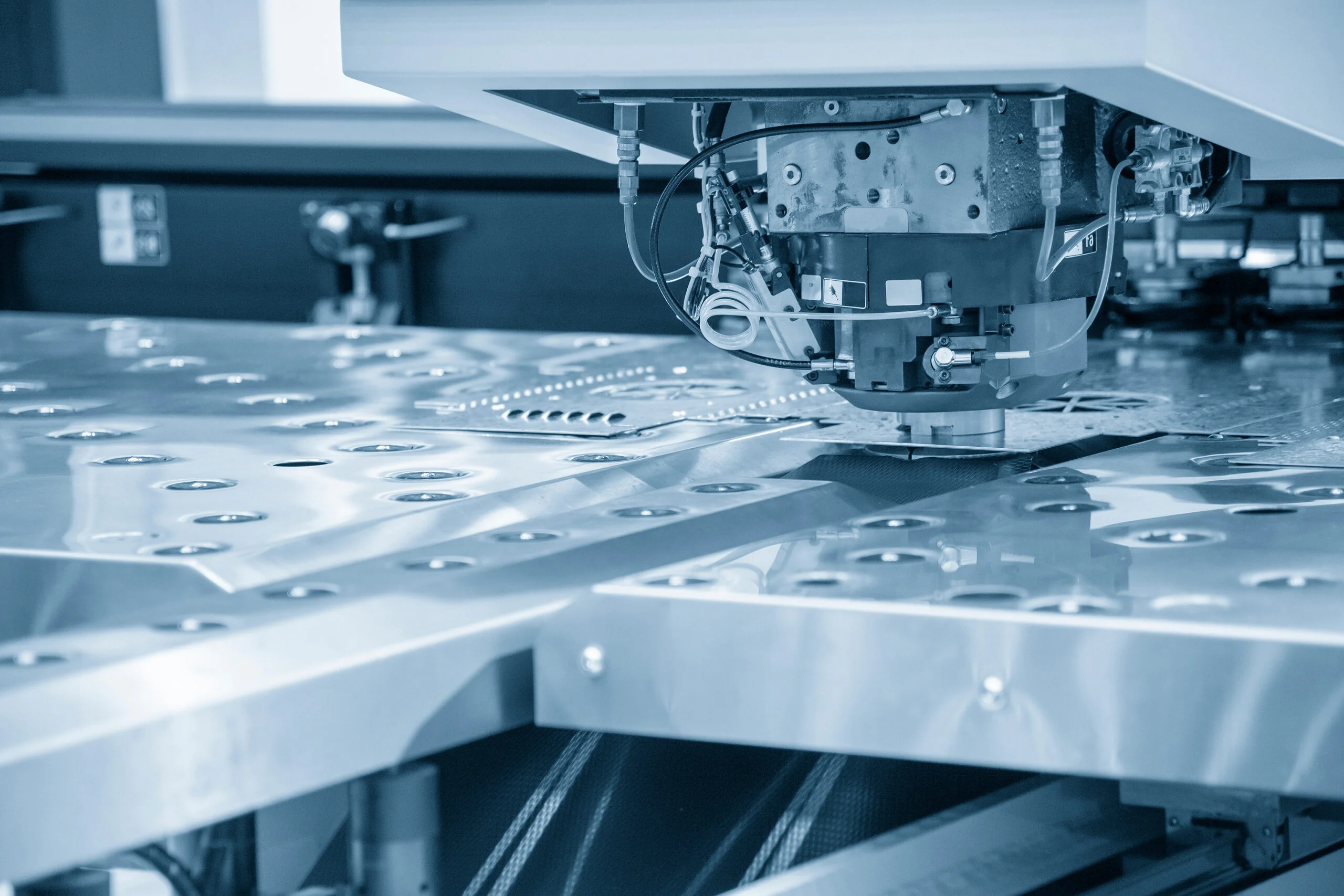
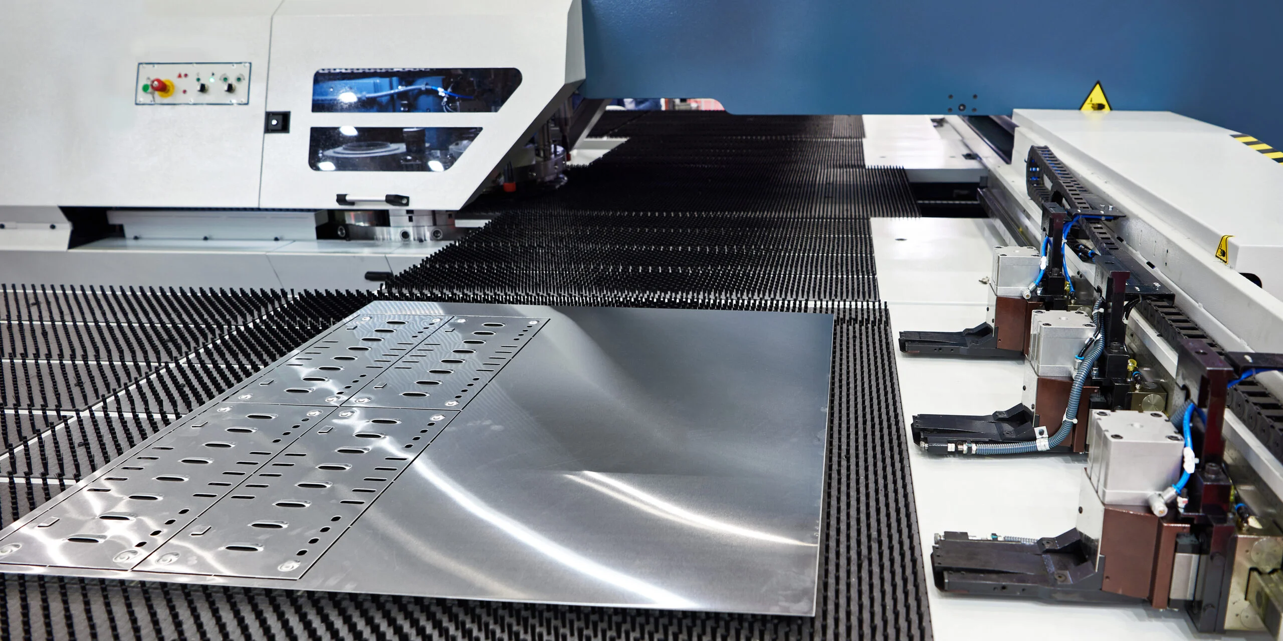
A CNC turret punch cuts and forms sheet metal using a selection of punch and die sets. The machine positions the punch or sheet under CNC control and indexes the required tool into position. It drives the punch through or into the material with a servo-electric, mechanical, or hydraulic punching system.
The turret holds a preloaded selection of tools for common holes, slots, and other shapes. Many tools are standard catalog items, though special geometries will typically need dedicated tooling. Once the appropriate tool is selected, a hole or formed feature is produced in a single stroke. So, for high-hole-count flat patterns, punching is often faster than laser cutting for common features.
The punching process also does work that a conventional 2D laser cutter cannot. Forming tools can produce louvers, lances, embosses, extrusions, bridges, and other 3D features without moving the part to a separate press. Turret tooling also supports operations such as marking, countersinking, deburring, and even some tapping applications.
Tooling has a big influence on part economics. A standard round, square, or obround (pill shape) punch will be available in the shop. A proprietary shape can require a custom punch and die, adding both cost and lead time. Where the geometry can be changed to use standard tooling without affecting function, the production cost may fall considerably. The benefit of this “whole feature in one action” becomes more pronounced as the feature count and production quantity increase.
Material thickness is the practical ceiling for turret punching that engineers often underestimate. Mild steel above about 6mm and stainless above 4mm may put you in territory where punch force requirements climb quickly—at that point laser cutting or waterjet is usually the more economical path and the fabricator will tell you so. Aluminum is more forgiving and punches well up to around 6mm depending on alloy.
Laser Cutting for Sheet Metal
Laser cutting uses a tightly focused laser beam to melt and vaporize a programmed 2D profile. There is no dedicated cutting tool whose geometry determines the shape, so a change from a round opening to a curved slot, or irregular cutout, only requires a program change.
That freedom makes laser cutting ideal for prototypes, evolving designs, complex contours, and low- to medium-volume parts. Fine internal geometry can also be easier to produce by laser, where a suitable turret tool is unavailable.
Laser cutting generally leaves a smoother continuous contour than a profile generated by successive punch hits. This is relevant on visible edges and openings, where appearance is more important.
Its limitation becomes apparent when the flat blank requires three-dimensional features. The laser can define their profiles, but it cannot emboss the sheet or form a louver. Those operations require other processes.
One distinction that matters for certain applications: laser cutting introduces a heat-affected zone at the cut edge—typically 0.1 to 0.5mm on stainless steel, varying with laser type, power, and feed rate. For most sheet metal work, this is a non-issue. Where it becomes relevant is precision hole sizing on interference-fit features, or on stainless grades where the HAZ can affect corrosion resistance along the edge. If either applies to your part, it is worth flagging on the drawing or raising with the fabricator before cutting starts. Turret punching produces no HAZ, which occasionally makes it the better choice for applications where edge metallurgy matters even when laser cutting would otherwise be preferred.
Turret Punch/Laser Combination Machines
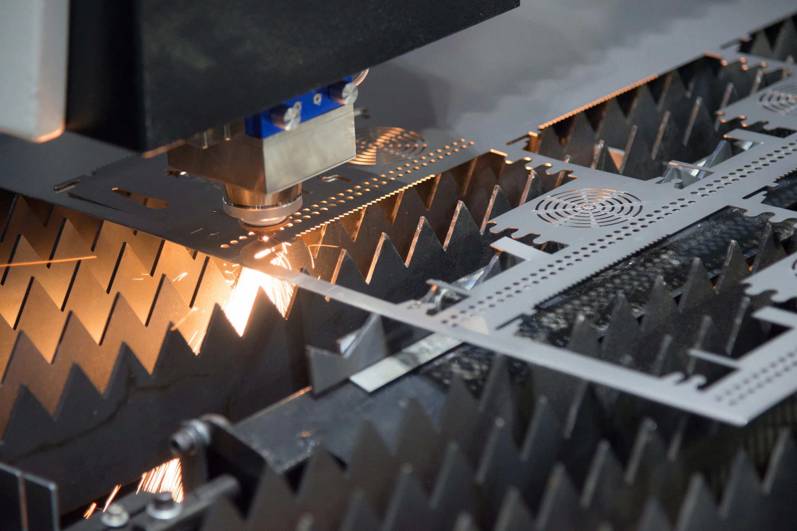
A punch/laser hybrid machine integrates CNC punching, forming, and laser cutting in one platform. It can punch repeated features and create formed details, and use the laser for complex contours, while the sheet remains referenced to the same table.
These machines exploit each process as appropriate, driven by an automated CAM software selection. A standard hole might be punched in one hit, a louver produced with a form tool, and an irregular outer profile cut with the laser.
This single-setup arrangement maximizes efficiency in the manufacture of mixed-feature components. It eliminates extensive intermediate handling and refixturing, which are time-consuming and introduce opportunities for alignment error between processes.
Combination processing does not automatically make every mixed-feature part cheaper. Machine availability, quantity, tooling, material, nesting, and cycle time all influence production flow. For appropriate geometry, however, completing the flat part in one manufacturing cell can transform your production rates.
Design Rules for Turret Punched Parts
Hole Size and Feature Spacing
For conventional turret punching, a minimum hole diameter equal to the material thickness is a rule-of-thumb for mild steel. This is a DFM guideline, rather than a universal process limit: minimum punch size also changes with material, tooling type, and machine capability.
Current guidance from Mate Precision Technologies, for example, gives minimum punch diameters relative to material thickness (T) for nonguided tooling:
- Mild steel: ≥ 1.0×T
- Aluminum: ≥ 0.75×T
- Stainless steel: ≥ 2.0×T
Fully guided tooling permits smaller ratios. AMADA also offers specialized tooling intended to punch holes substantially smaller than the sheet thickness.
A drawing therefore should not impose the 1×T guideline as a hard limit. If a 1.5 mm sheet genuinely needs a 1 mm hole, the fabricator can determine whether suitable tooling is available, or whether that feature requires a laser cut.
Hole spacing deserves similar attention. As a starting point (T = material thickness, R = inside bend radius):
- Hole-to-hole spacing: ≥ 2×T
- Hole-to-edge distance: ≥ 1.5–2×T, to avoid distortion as the punch shears and displaces material
- Formed features (louvers, embosses, lances) to bend line: ≥ (2–3)×T + R, depending on source and feature size, to avoid distortion during subsequent bending
There is no universal spacing rule for every combination of form height, bend radius, material, and orientation. Give forms enough clearance during initial design, and involve the fabricator where the feature approaches the bend zone.
Nibble Marks
Larger openings and curved profiles can be generated by nibbling, where a smaller punch makes a sequence of overstepped hits. The trade-off appears at the cut edge. Each hit intersects the previous one and leaves a small scallop, producing the characteristic nibble marks seen on punched curves. Increasing the overlap between hits can reduce their prominence, although this increases cycle time.
If a curved opening is cosmetic, forms a visible product edge, or needs a consistently smooth contour, identify that requirement. The fabricator can then laser cut the feature, select different tooling, or account for finishing, rather than discovering the surface requirement after the parts have been punched.
Slugs and Surface Marking
Every punched through-hole also creates a slug. Normally it falls through the die, but small slugs can occasionally be pulled upward with the punch. A loose slug trapped between the sheet and tooling can mark the surface or interfere with subsequent punching.
This demands more attention on cosmetic stainless panels, painted/plated components, and other parts where surface condition must meet a defined standard. The designer should still call out cosmetic surfaces rather than assume that all as-punched faces will remain pristine.
Choosing Between Punch, Laser, and Combination
Choose turret punching for high-volume parts with many repeated holes or standard formed features, where fast cycle times and low per-part tooling cost outweigh the need for a dedicated setup. Choose laser cutting for low-to-medium volumes, complex 2D profiles, and frequent design changes, where no dedicated tooling means a program change is the only cost of revision. Choose a combination machine when a single part needs both repeated punched or formed features and a complex laser-cut contour, since both operations complete in one setup without refixturing.
Punch vs. Laser vs. Combination
| Factor | CNC turret punch | Laser cutting | Punch/laser combination |
| Louvers, embosses and other forms | Yes | No | Yes |
| Repeated standard holes | Very efficient | Suitable | Very efficient |
| Complex contours | Possible, but nibbling may mark the edge | Well suited | Well suited |
| Small punched features | Tool and material dependent | Fine features possible within laser/process limits | Use the appropriate process for each feature |
| Hard tooling | Standard or custom punch tooling | No profile-specific hard tooling | Punch tooling where required |
| Design changes | May require different/custom tooling | Usually programming change | Laser provides flexibility for changing contours |
| High hole count | Strong application | Cut time accumulates around each feature | Strong application |
| Curved edge appearance | Nibble marks possible | Continuous laser-cut contour | Laser can be used on visible contours |
| Formed and complex features on one part | May require additional processing | Requires separate forming operation | Strong application |
Custom tooling is difficult to justify for limited prototypes, but its cost is insignificant when amortized across thousands of parts. Likewise, eliminating seconds from each feature may matter little on ten components, but be a serious cost benefit in a sustained production run.
Matching Process to Part Type
Good fit for turret punching:
- Enclosure panels and brackets with many repeated standard holes across a production run
- Parts needing louvers, lances, or embossed ribs for ventilation, grounding, or stiffening
- Chassis parts using extruded or bridged features for self-clinching fasteners
Good fit for laser cutting:
- Prototype or low-volume brackets and enclosures where the design is still changing
- Parts with complex, irregular, or curved 2D contours and no repeated standard features
- Cosmetic panels or bezels where a smooth, continuous cut edge matters
Good fit for a punch/laser combination:
- Enclosures or chassis that combine a repeated hole or louver pattern with an irregular outer profile or cosmetic cutout on the same part
- Mixed-feature production parts where refixturing between processes would add cost or alignment risk
Designing Without Specifying the Wrong Process
The drawing should describe only the finished part, wherever the manufacturing method is not functionally decisive. Calling out a laser-cut hole when a punched hole would perform identically bars a lower-cost option. Specifying punching on a cosmetic contour can create poor quality outcomes.
Put the manufacturing restriction on the drawing when it serves a real purpose. Surface appearance, burr direction, edge condition, feature geometry, and local distortion may justify process prescription.
This is particularly useful for sheet metal prototyping that may later move into production. Early quantities can be laser cut without dedicated tooling. Once volumes rise, repeated features may migrate to turret punching, while the part geometry and functional requirements remain unchanged.
A version of this problem: an engineer specifies “laser cut all openings” on a production enclosure because the prototypes were laser cut. The fabricator prices it with laser cutting throughout. A different fabricator, working from the same drawing without that restriction, punches the mounting holes at a fraction of the time and quotes it lower. The parts are identical, but the process restriction costs money without providing any benefit.
Fictiv’s sheet metal manufacturing network supports laser cutting, turret punching, and punch/laser combination fabrication from prototype through production. DFM review can identify features that are expensive or troublesome to punch and determine where a geometry change, standard punch, or laser-cut feature may provide a better option.
Ready to manufacture a sheet metal part? Upload your CAD files and drawings to get a quote and DFM feedback from Fictiv.
Talk to a Fictiv expert about your project, or upload your parts to start a free quote.
FAQs About Turret Punching + Laser Cutting
What is CNC turret punching?
CNC turret punching cuts and forms sheet metal using a preloaded selection of punch and die sets under CNC control. The machine indexes the required tool and drives it through the material in a single stroke, using a servo-electric, mechanical, or hydraulic system. Because each hit produces a complete feature at once, it’s typically faster than laser cutting for parts with many repeated holes or standard forms.
Is turret punching still used for production, or has laser cutting replaced it?
Turret punching remains widely used for production work despite being the older technology. Laser cutting has largely taken over prototyping and low-volume, high-change work because it needs no dedicated tooling, but punching stays competitive — and often faster — for high-hole-count flat patterns and parts that need forming operations a laser cutter can’t perform.
What’s the difference between a laser-cut edge and a punched edge?
Laser cutting leaves a smooth, continuous contour, since the beam follows a programmed path rather than a series of tool hits. Punched curves are typically produced by nibbling — overlapping hits from a smaller punch — which leaves small scallops called nibble marks at each intersection. For cosmetic or visible edges, that difference should be called out on the drawing.
What’s the minimum hole size a turret punch can produce?
A common rule of thumb is a minimum hole diameter equal to material thickness for mild steel, but the real limit depends on tooling. Mate Precision Technologies, for example, cites nonguided-tooling ratios of 1:1 for mild steel, 0.75:1 for aluminum, and 2:1 for stainless steel, with fully guided tooling permitting smaller holes still. It’s a guideline to confirm with the fabricator, not a hard limit.
When does a punch/laser combination machine make sense over a single process?
A combination machine is worth it when a single part needs both repeated punched or formed features and a complex or irregular laser-cut contour, since it handles both in one setup without refixturing. It doesn’t automatically make every mixed-feature part cheaper — machine availability, quantity, and tooling still factor in — but for the right geometry it can meaningfully improve production rates.