


Time to read: 19 min
Great machine design engineers need more than just a strong technical base. They must also know how to select the best components for a given project. That includes which parts to buy from a catalog and which ones to custom design and manufacture.
Standard and configurable components like bearings, gears, linear rails, and fasteners are rarely designed from scratch, nor should they be. Instead, an engineer will specify and buy them off the shelf (OTS). Custom parts designed specifically for one machine are what tie them together into a complete mechanical system.
This guide takes a machine builder’s perspective on traditional machine design fundamentals. It covers not just when to specify an off-the-shelf component versus design custom geometry, but how the two interface. It walks through the engineering fits, tolerances, and design considerations across the part types that show up in nearly every machine: fasteners, bearings, shafts, gears, structural frames, and linear and rotary motion systems.
Download the full Machine Design Guide eBook PDF to keep on hand as a reference.
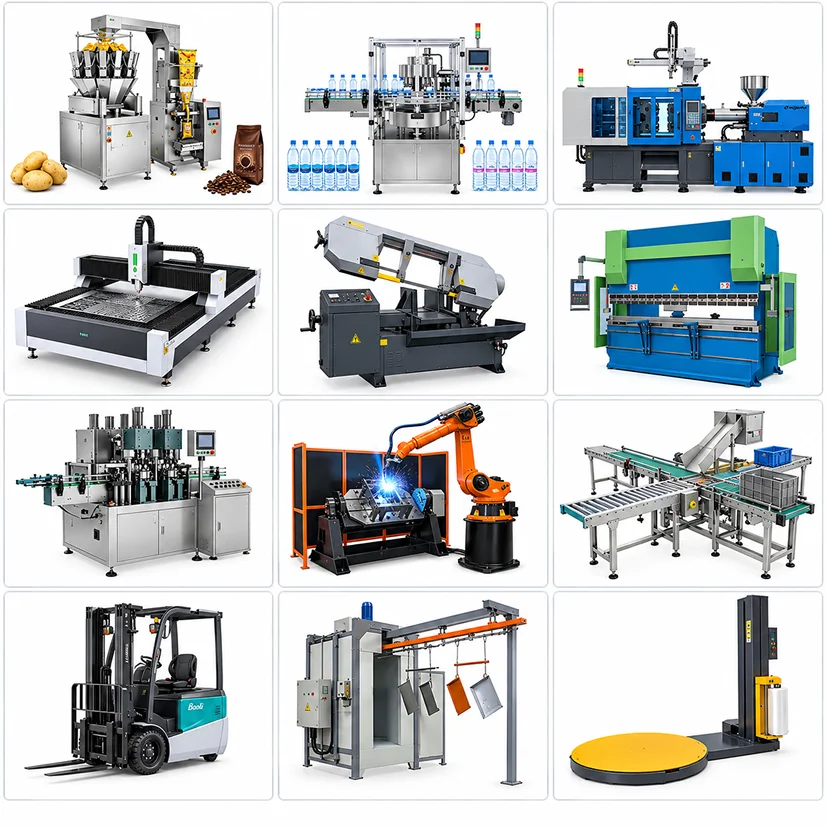
Common industrial machines can span packaging (weighers, fillers, stretch wrappers), fabrication (injection molding machines, laser cutters, press brakes), or automation and material handling (robotic welding cells, conveyors). Each is built from the same ethos of off-the-shelf components and custom parts.
The Machine Design Process
Machine design rarely moves in a straight line. It progresses through an iterative engineering process in which analytical findings and physical testing continually refine initial assumptions. An idealized machine design process includes the following steps:
- Identification of Needs: Define clear operational objectives, environmental conditions, motion requirements, load cycles, target lifespan, and production cost limits.
- Conceptualization: Architecture drafting, kinematic evaluation, spatial packaging, and evaluation of initial build-versus-buy trade-offs across subassemblies.
- Analysis: Apply static, dynamic, fatigue, and deflection calculations to determine critical dimensions, select materials, verify stock catalog items, and shape custom part geometry.
- Prototyping: Build physical representations, ranging from rapid 3D-printed fit checks to functional CNC-machined metal prototypes, to validate assembly interfaces and real-world kinematics.
- Refinement: Optimize part geometry per Design for Manufacturing (DFM) guidelines, adjusting tolerances based on physical-fit feedback, and fine-tuning material selections.
- Production: Scale fabrication through production-grade tooling, automated CNC manufacturing, batch sheet metal production, and rigorous assembly quality checks.
Integrating Custom and Off-the-Shelf Components in Machine Design
The choice between purchasing a standard catalog component or designing a custom-manufactured part should be evaluated at the earliest design stages, and every stage in the development process that follows. The longer you wait, the more you risk locking a component into your BOM that isn’t the best choice.
The Buy/Make Decision Framework: 5 Questions to Ask at Each Development Stage
The following five-question framework can be applied to each component to determine whether an OTS part will suffice—or whether a custom part is needed instead.
- Is the component standardized across industry?
If yes, use off-the-shelf parts, as long as they fit your design requirements.
- Does custom geometry unlock core performance, mass reduction, or spatial compacting?
If so, custom may be worth the added cost and complexity—but only if the performance gain justifies it.
- What is the true total cost of ownership?
When evaluating a custom option, consider the full program cost, not just unit price. That includes tooling and non-recurring engineering (NRE) costs weighed against the off-the-shelf alternative.
- How do lead times impact overall schedule risk?
Before making a final call, compare the lead times for custom and standard options. Make sure to also consider the relative sourcing and supply chain risks.
- Can custom geometry absorb manufacturing variations of surrounding catalog parts?
If the assembly can be improved with custom components by reducing part count and tolerance stackup, this is another reason to select a custom part.
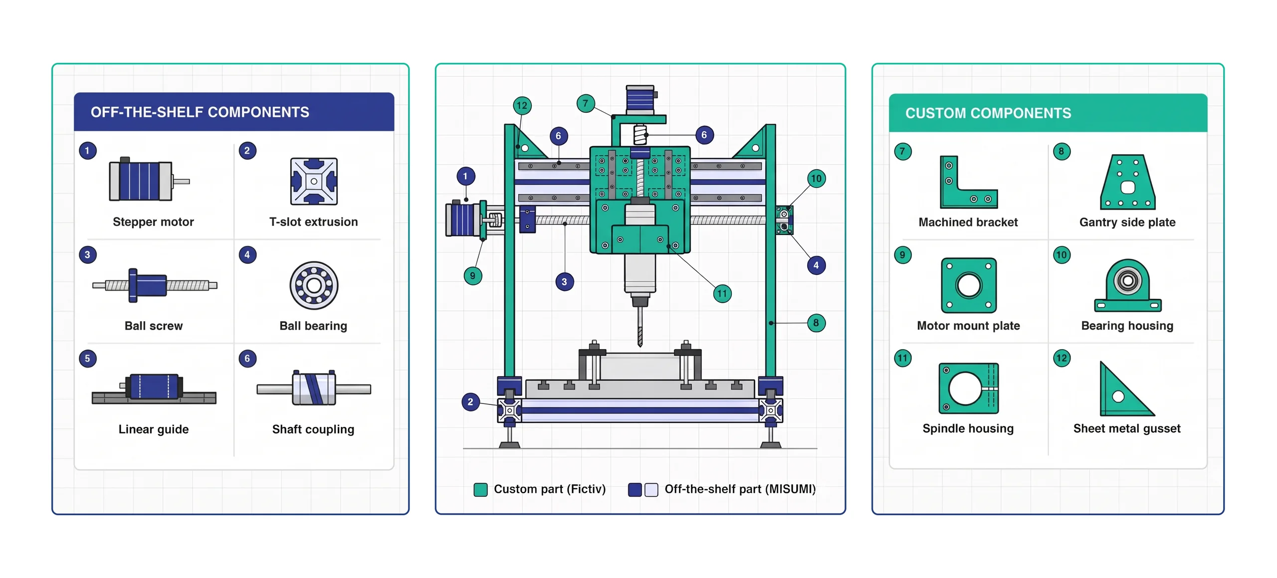
Beyond this framework, your decision should also account for the engineering fundamentals. Standard components typically come with established specs based on vendor test data, while custom parts usually require validation through Finite Element Analysis (FEA) and physical testing.
The Analytical Foundation – Machine Design Theory
Catalog components and custom parts are evaluated against the same three fundamentals that govern any mechanical component: stiffness and deflection, stress and failure, and dynamics and vibration.
Fundamental #1: Stiffness and Deflection
Deflection frequently governs machine design long before stresses approach material yield limits. Cantilevered brackets, drive shafts, structural frames, and long, unsupported spans can experience functional failure if excessive deflection impairs gear mesh alignment, binds linear bearings, or breaks environmental seals.
Rigidity is driven by both Young’s Modulus and cross-sectional area moment of inertia. This means structural stiffness can often be engineered through smart geometric cross-sections before resorting to denser or more expensive materials.
For a cantilevered bracket under a point load at its free end, deflection follows:
δ = FL³ / (3EI)
where:
δ = deflection at the free end
F = applied point load
L = unsupported (cantilever) length
E = modulus of elasticity of the material
I = area moment of inertia of the cross-section
Deflection scales with the cube of unsupported length, which is why reducing span or increasing cross-sectional moment of inertia (I) usually beats switching to a stiffer, pricier material.
Fundamental #2: Dynamics and Vibration
Machines operating near a natural frequency can amplify vibration and cyclic loads beyond what static calculations predict. Check natural frequencies and shaft critical speeds against expected excitation frequencies to identify resonance risks.
A structure’s natural frequency rises with stiffness and falls with mass. A useful estimate comes straight from its static deflection under its own weight.
For a uniform shaft on simple supports, the fundamental natural frequency is:
ωn = (π² / L²) × √(EI / ρA)
where:
ωn = fundamental natural frequency of a uniform, simply supported shaft (rad/s)
L = shaft span length
E = shaft material modulus of elasticity
I = area moment of inertia of the shaft’s cross-section
ρ = density of the shaft’s material
A = cross-sectional area of the shaft
In Hz: fn = ωn / 2π
Because L and EI are the same geometric levers that govern static deflection, a shaft stiffened to control deflection often raises its natural frequency, as well. Note, however, that this should be verified rather than assumed, since added material increases both mass and stiffness.
Fundamental #3: Stress and Failure Modes
When designing machines, you should be cognizant of applied stresses and three common failure modes: static yielding, high-cycle fatigue, and elastic instability. Stress concentrations drive the first two failure modes, and controlling them is cheapest during conceptual design before locking in geometry that could require expensive tooling changes.
The relationship between a geometric discontinuity and local stress concentration is straightforward:
σmax = Kt × σnom
where:
σnom = nominal stress from basic loading
σ = F/A for axial loading
σ = Mc/I for bending
Kt = geometric stress-concentration factor
Kt is the geometric stress-concentration factor for the specific geometry ratio—which is exactly why geometry, not material grade, is the first lever against fatigue failure.
Two qualifications matter in practice. Under static load, a ductile material yields locally at the notch and redistributes the peak. Kt is therefore customarily neglected for static analysis of steel and aluminum—it is applied statically only to brittle materials such as grey cast iron. Under fatigue load, the governing factor is not Kt but the fatigue stress-concentration factor:
Kf = 1 + q(Kt − 1)
where q is notch sensitivity, a function of notch radius and the material’s ultimate tensile strength.
Geometry is the first lever against fatigue. But the notch sensitivity that converts geometry into a fatigue penalty is itself a material property—a higher-strength steel is more notch-sensitive, not less. Specify both to size the fatigue margin correctly and reduce risk of design failure.
Material Selection Matrix for Machine Design
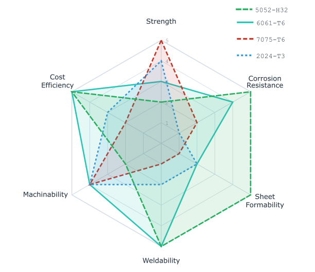
Most machine design parts come from a well-established set of materials. The table below covers the grades that show up most often, along with their yield and tensile strengths, typical applications, and suitability for common manufacturing processes.
Keep in mind that the best material on paper isn’t necessarily the right choice in practice. If a vendor doesn’t have the machining capabilities or can’t source it with sufficient lead time, the design also needs to account for that.
| Material Grade | Strength (MPa) | Primary Applications | Process Suitability |
| Aluminum 6061-T6 | Yield ~276 Tensile ~310 | Machine frames, mounting plates, fixture plates, housings | Excellent CNC Milling/Turning, Sheet Metal |
| Aluminum 7075-T6 | Yield ~503 Tensile ~570 | Highly stressed structural brackets, high-speed arms | Excellent CNC Machining; Poor Weldability |
| AISI 1018 Steel (CD) (cold-drawn) | Yield ~370 Tensile ~440 | Machine frames, low-stress shafts, pinions, weldments | Superior Weldability, Good Machining |
| AISI 4140 Steel (HT) (mid-temper condition) | Yield ~750 Tensile ~950 | Heavy-duty shafts, precision gears, power screws | CNC Turning, Gear Hobbing, Heat Treating |
| 304 Stainless Steel | Yield ~210 Tensile ~565 | Food processing equipment, chemical housings, washdown frames | Good Machining, Excellent Welding, Laser Cutting |
| Acetal (POM-C) | Yield ~55 Tensile ~65 | Wear strips, low-load gears, insulating spacers, bushings | Exceptional CNC Machining, Injection Molding |
Engineers can streamline selection using digital tools like Fictiv’s Materials.AI to rapidly cross-reference mechanical limits, chemical compatibility, and process availability across hundreds of material options.
Designing Machines Around Standard Components
The overwhelming majority of machine subassemblies convert, transmit, or support either rotary or linear motion. The core motion elements (bearings, shafts, rails, screws, fasteners) are OTS components. The custom parts around them do two jobs: they locate each catalog component accurately, and they support it stiffly enough that it performs to its rating. A precision bearing in a poorly toleranced housing is only as good as the housing. System reliability comes from getting that interface right.
Fasteners and Joints
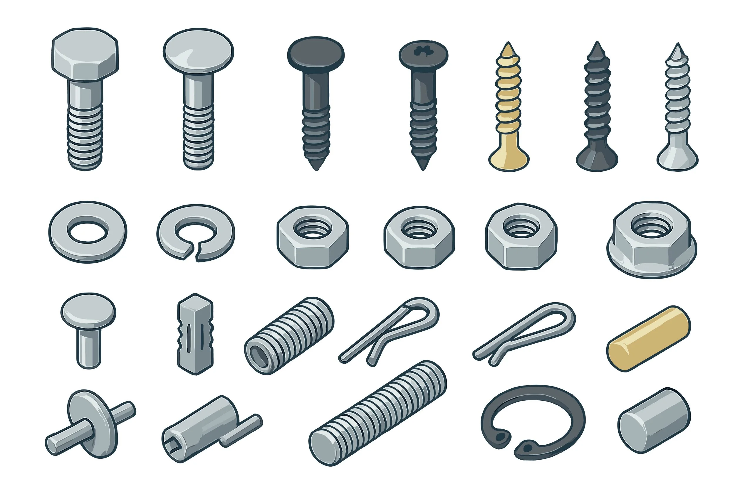
Fasteners are the most universal OTS component in any machine, and the clearest example of the buy/make split. Nobody designs a bolt from scratch, but the hole it threads into and the parts it clamps are often custom, and threaded joints are common failure points. A couple considerations:
- Threaded mechanical fasteners are specified by diameter, pitch, property class, head geometry, and finish, but the joint’s behavior comes down to preload. Sufficient preload maintains clamping pressure under cyclic operational loads and prevents dynamic stress from fully transferring into the thread roots, where fatigue failure could initiate.
- Thread engagement is sized so the internal threads develop the fastener’s full tensile strength. The tapped material should not be the weak element unless that is a deliberate choice. Because engagement scales inversely with the tapped material’s strength, softer materials need longer engagement, not shorter:
| Tapped Material | Minimum Engagement |
| Steel, approx. same strength as fastener | 1.0 x D |
| Cast iron, brass, bronze | 1.5 x D |
| Aluminum alloys | 1.5 – 2.0 x D |
| Magnesium, zinc, reinforced thermoplastic | 2.0 – 2.5 x D |
For critical joints, calculate the length of engagement from the shear-area relation in Machinery’s Handbook (per FED-STD-H28) rather than a rule of thumb, and check the tapped material’s shear strength directly. Where engagement is limited by wall thickness, a thread insert (steel bushing or wire insert) restores full bolt capacity in a thin aluminum boss.
Springs
Standard: Helical compression, extension, and torsion springs are commonly selected from standard catalogs based on required spring rate, free length, operational stroke, and material grade. Hard-drawn wire is a good fit for general static applications, while materials like chrome-vanadium steel are used for dynamic, high-temperature, or severe fatigue conditions. Belleville conical washers (disc springs) offer effective solutions for extremely high loads in axially constrained spaces.
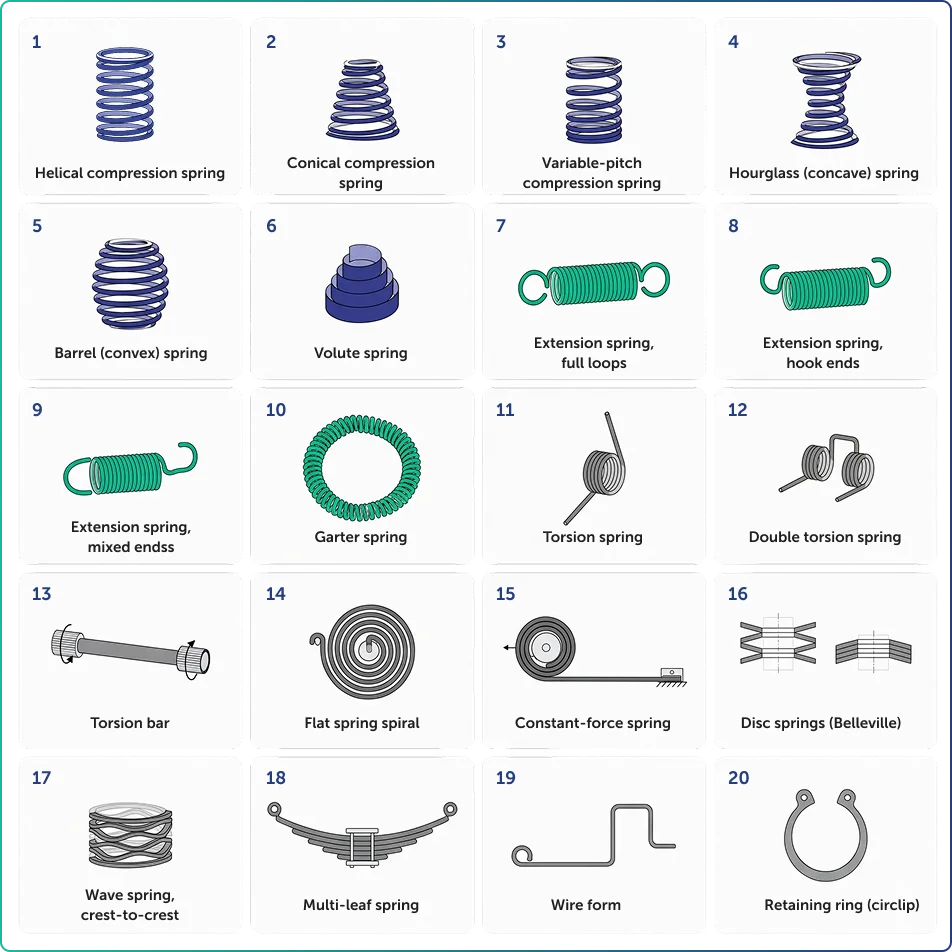
Custom: Custom spring seats, retaining guide pins, and pockets must be accurately dimensioned with correct tolerances. The depth tolerance of a custom machined spring pocket directly dictates installed spring preload; tight pocket-depth tolerances are essential for consistent operational return forces. These features are often CNC-machined into a plate or housing that holds the spring.
Bearings
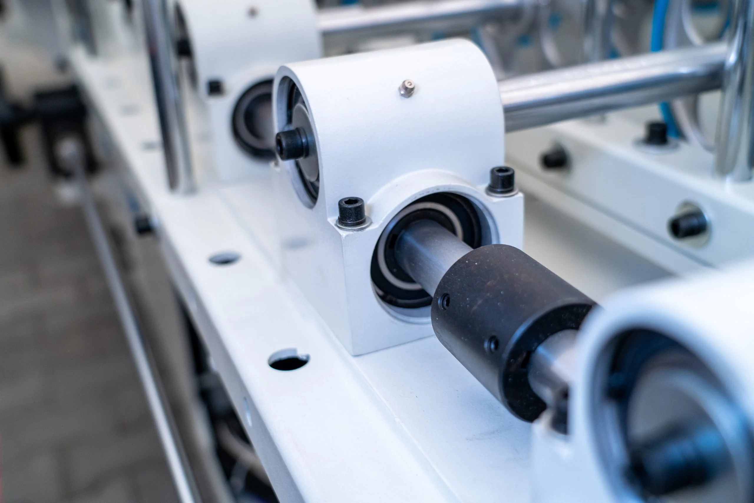
Standard: Rolling-contact bearings (ball, spherical roller, tapered roller) are selected using speed limits and the ISO 281 / ISO L10 bearing life equation to match expected radial and axial load vectors. Plain bronze or engineered polymer bushings serve as compact alternatives for high-load, low-velocity, or oscillating motions.
Custom: The custom housing bore surrounding a rolling bearing dictates its operational life. Machine designers must specify correct housing fit classes (e.g., ISO H7 for clearance/slip fits, P7 for tight press fits), shoulder heights to properly back up bearing rings, snap ring retaining grooves, and thermal expansion relief spaces. Over-tight housing bores squeeze internal bearing clearance, inducing severe heat buildup and premature binding. These bores are typically CNC turned or bored to hold the required ISO fit class.
Shafts
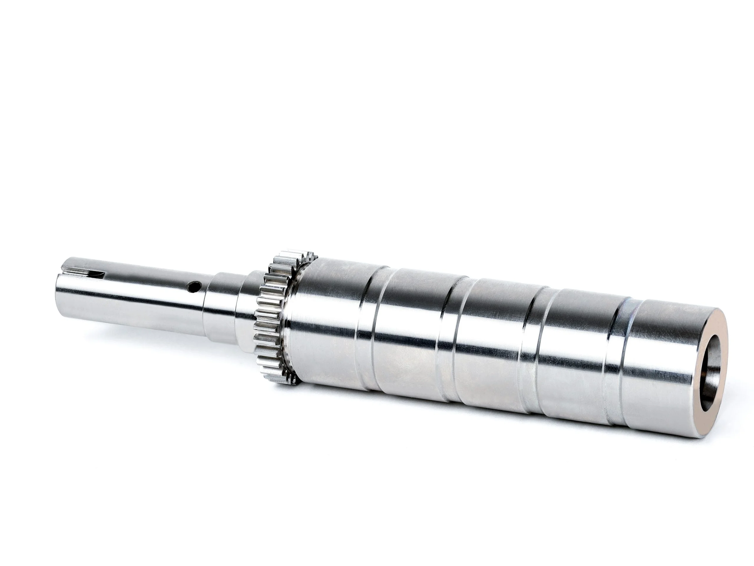
Standard: Ground precision steel shafts with standard and configurable dimensions are available off the shelf for linear bushing integration and basic torque transmission drives.
Custom: Power transmission shafts usually require custom turning, stepped journals, keyways, or splines. Because rotating shafts experience combined bending and torsional stress cycles, every shoulder diameter step must include smooth transition fillets to reduce stress concentration. Furthermore, shaft deflection calculations must ensure bending angles at bearing locations stay within manufacturer limits.
Gears and Power Transmission
Standard: Gears (spur, helical, bevel, worm) are selected by diametral pitch/module, pressure angle, tooth count, and AGMA quality ratings. Synchronous timing belt drives and roller chains offer nonslip torque transmission across wide center distances.
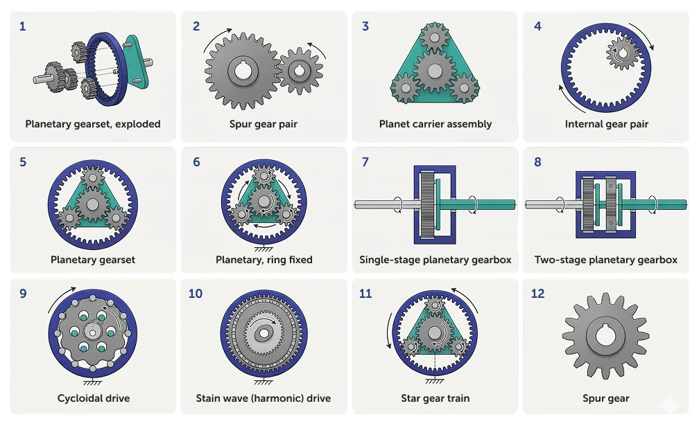
Custom: Gear performance relies entirely on the accuracy of custom gearbox housings and mounting plates. Shaft center-to-center distance tolerances must be tightly controlled to prevent gear binding or excessive tooth backlash. Custom housings should incorporate oil fill/drain ports, shaft seal counterbores, and stiff internal ribbing to maintain center-distance alignment under heavy torque loads.
Structural Elements and Frames
Standard: Modular T-slot aluminum extrusion framing systems allow fast, adjustable structural assembly using simple hand tools without welding or precision machining.
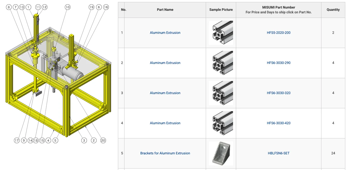
Custom: Where high structural rigidity, dampening, or high precision is required, custom welded structural steel frames or thick CNC-machined baseplates are necessary. DFM best practices for custom frame plates involve designing features so that all critical mounting surfaces can be machined in a single setup, eliminating cumulative datum alignment errors.
Sheet metal brackets and frames also add structure and rigidity with less material. These components can also be welded and joined with self-clinching fasteners to minimize assembly steps.
Linear Motion Components
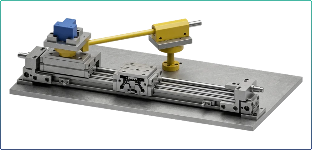
Standard: Profile linear rails, ball runners, lead screws, and recirculating ball screws are catalog items defined by load rating, stroke length, positioning accuracy grade, and carriage preload. Ball screws deliver high efficiency for dynamic positioning, while lead screws offer self-locking safety in vertical lifting applications.
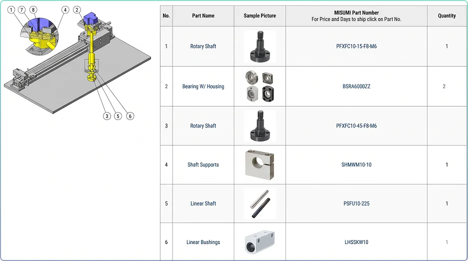
MISUMI Americas offers configurability of off-the-shelf components, allowing customization of standard parts
Custom: Custom carriage adapter plates, motor mounts, and end-bearing mounting blocks must hold strict parallelism tolerances. Mounting twin linear rails on non-parallel custom base surfaces induces severe mechanical binding, leading to rapid wear and motor overload.
Where a rotary motor drives a linear axis through a gearbox, coupling, and screw, positioning accuracy depends on more than the screw’s own lead accuracy. Each coupling introduces backlash or torsional lash, and any misalignment between motor shaft and screw shaft translates into radial loading on the screw’s support bearings rather than clean torque transfer. Specifying a flexible coupling sized for the expected misalignment, and budgeting lash across the full gearbox-coupling-screw chain, is often what separates a linear axis that holds its rated accuracy from one that doesn’t.
Rotary Motion Components
Standard: Rotary motion systems transmit torque from a motor through a drivetrain—coupling, shaft, bearings—to an output such as a gear, pulley, cam, or direct-drive load. The core catalog components are well-standardized: shaft couplings, shaft collars, timing pulleys and belts, sprockets, and rotary bearings are all available as configurable off-the-shelf items. Coupling selection matters more than engineers often expect. Jaw couplings tolerate moderate misalignment and suit general-purpose motor connections. Bellows couplings provide near-zero torsional lash for precision positioning. Oldham couplings handle larger parallel offsets without transmitting bending loads to shaft bearings. Budgeting cumulative lash across the full motor-coupling-shaft-output chain determines whether a rotary axis holds its rated accuracy.
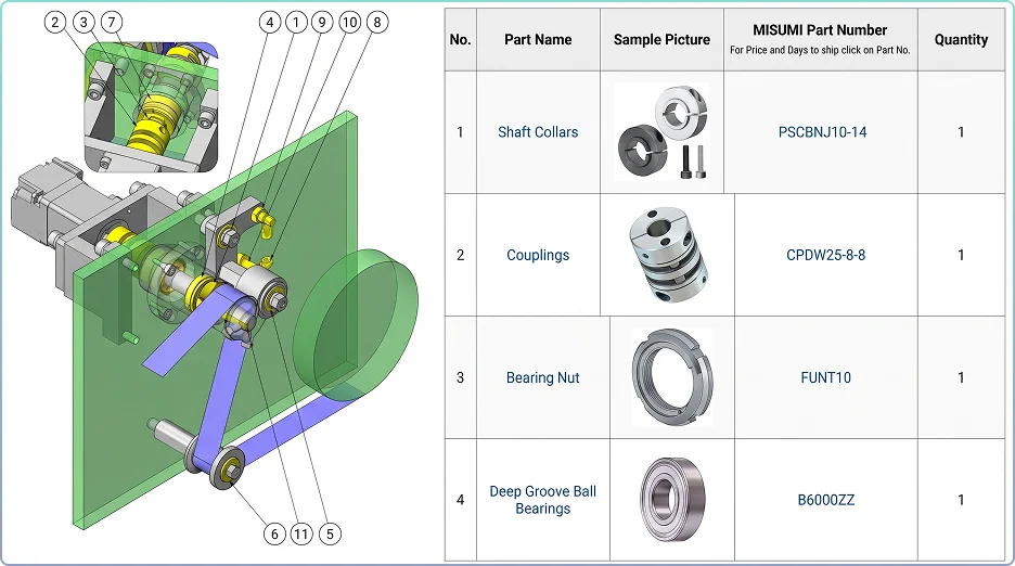
Custom: Custom geometry in a rotary system is primarily the motor mounting plates, output flanges, and bearing support structures that locate shafts, carry bearing loads, and seal against contamination. These parts must maintain shaft parallelism or concentricity across the full assembly. These tolerances are easy to specify, but also easy to lose if mounting surfaces aren’t machined in a single setup.
Shaft sealing interfaces—lip seal bores, labyrinth grooves, O-ring counterbores—are dimensionally critical. A lip seal bore out of round produces uneven contact pressure and premature seal failure. Other drivers are shaft surface finish, shaft hardness, and dynamic runout at operating speed, not bore roundness alone.
Critical speed should always be considered when designing for rotary motion. The critical speed of a shaft is where the speed of rotation matches the natural frequency of the system. This can cause immediate structural failure, which makes it highly dangerous to operate at critical speed continuously. Note that critical speed is different from the maximum safe operating speed. Shaft critical speed is the rotary equivalent of deflection. As operating speed approaches the shaft’s first bending natural frequency, deflection amplitudes grow rapidly and bearing loads follow.
The standard design target is to keep the operating speed at half the critical speed at most, assuming a factor of safety (FOS) of 2.
Industrial rotating-machinery standards like API 684 refine this further with a required separation margin around every critical speed, sized to the rotor’s damping characteristics rather than a fixed ratio. A sharply resonant, lightly damped rotor therefore needs a wider buffer than a well-damped one.
Tolerance and Fits: Where Design Meets Manufacturing
Unnecessarily tight tolerances drive production costs up exponentially, while overly loose tolerances result in nonfunctional assemblies. Mastering engineering fits, stack-up analysis, and standardized Geometric Dimensioning and Tolerancing (GD&T) bridge the gap between design intent and physical manufacturing.
Standard Fits
- Clearance Fits: Guarantee a physical gap between mating parts, which is essential for sliding shafts, rotating bushings, and removable locating pins.
- Transition Fits: Provide precise spatial alignment where parts may fit snugly without binding. This often requires light tapping with a dead-blow mallet during assembly.
- Interference Fits: Ensure continuous surface pressure across mating boundaries by locking parts together semi-permanently for torque transfer without the need for keys or setscrews.
Tolerances
When applying GD&T fundamentals, ASME Y14.5-2018 acts as the primary governing standard across North America. Internationally, the equivalent isn’t one document but the ISO GPS suite (ISO 8015, 1101, 5459, 2692). The defaults are actually reversed, not just different. ASME’s envelope principle ties form to size by default, while ISO’s Independency Principle controls size and form separately unless a relationship is explicitly stated.
Designing for Machine Assembly
While DFM governs how efficiently an individual part can be manufactured, Design for Assembly (DFA) governs how efficiently and reliably those parts come together into a finished machine.
DFA principles reduce assembly labor and cut error rates on the line. They also eliminate costs that DFM alone can’t touch, since the cheapest part to make is still expensive if it takes five extra minutes and a skilled technician to install correctly.
Some good rules of thumb:
- Reduce part count wherever function allows. Every part eliminated is one less component to source, inspect, handle, and potentially install backward. Consolidating a multi-piece bracket into a single custom-machined part often costs less in aggregate once you factor in the assembly labor it removes.
- Design in self-locating and poka-yoke features: chamfered lead-ins, asymmetric pin patterns, and keyed mating geometry.
- Standardize fasteners across the assembly. Limiting a design to two or three thread sizes and head styles reduces tooling changeovers on the line and lowers the chance of the wrong fastener ending up in the wrong hole.
- Sequence assembly access deliberately. Fasteners, connectors, and adjustment points should remain reachable at each stage they’re needed.
- Favor symmetry, or make asymmetry obvious. Symmetric parts can be installed without orientation checks. Where asymmetry is functionally required, exaggerate it so the part is physically difficult to install incorrectly.
Design for Manufacturing and Assembly (DFMA) turns the buy/make decision framework introduced earlier in this guide into a build-time advantage: a custom part designed with assembly in mind is easier to build correctly, and can also cost less to manufacture than a design that isn’t optimized.
For machine design assembly, also consider selecting the appropriate assembly techniques:
- Threaded Fasteners: Provide reusable, field-serviceable joints.
- Welding: Delivers high rigidity and permanent structural connection for heavy metal frames.
- Structural Adhesives & Snap Fits: Enable rapid, low-weight assembly for high-volume polymer enclosures.
- Heat Staking and Ultrasonic Welding: Reduce part count and enable sealed joints.
Prototyping & Manufacturing Process Selection
Utilizing different prototyping methods at different design stages allows engineering teams to validate form, fit, and mechanical function systematically. Features acceptable in a prototype, like simplified welded joints or manually tapped holes, may not scale directly to automated high-volume production. Engineers should explicitly flag prototype-specific deviations in design documentation.
During the machine design process, selecting the appropriate primary manufacturing method lowers unit cost while optimizing mechanical performance for custom machine geometries. Each manufacturing method carries unique geometric constraints and DFM guidelines.
From Machine Design to Full Production
Machine design is the skill of making informed engineering decisions at the intersection of mechanical function, manufacturability, and cost. Successful engineers evaluate off-the-shelf specs and custom geometry together, so every assembly transitions smoothly from concept sketch to production floor.
Ready to streamline your next machine build? Create your free Fictiv account today to upload your 3D CAD models, receive instant DFM feedback, and access our global network for rapid prototyping and production manufacturing.
Talk to a Fictiv expert about your project, or upload your parts to start a free quote.
FAQs About Machine Design
How do you decide whether to buy a component off the shelf or design it custom?
Run it through five questions as early in the design as possible: Is the component standardized across industry? Does custom geometry unlock core performance, mass reduction, or spatial compacting? What’s the true total cost of ownership? How do lead times affect schedule risk? And can custom geometry absorb manufacturing variation in the catalog parts around it? A component that looks like an obvious buy on cost alone can still need to be custom if it has to absorb tolerance stack-up from the parts around it.
What are the most common ways a machine part fails?
Three mechanisms cover most machine design failures: static yielding (the part permanently deforms under load), high-cycle fatigue (repeated stress below the yield point eventually cracks the part), and elastic instability, or buckling (a slender part under compression suddenly bows out). Stress concentrations at geometric discontinuities, sharp corners, and sudden diameter changes drive the first two, which is why controlling geometry early is the cheapest lever against failure.
What is critical speed, and why does it matter for a rotating shaft?
Critical speed is the rotational speed at which a shaft’s operating frequency matches its own natural frequency, causing deflection and vibration to spike sharply and risking structural failure. The standard design target is to keep the operating speed at half the critical speed or lower, and industrial standards like API 684 refine that further with a damping-based separation margin rather than a fixed ratio.
How much thread engagement do I need for a tapped hole?
It depends on the tapped material’s strength relative to the fastener. As a rule of thumb, steel tapped to roughly the fastener’s own strength needs about 1x the fastener diameter (D) of engagement; cast iron, brass, and bronze need about 1.5x D; aluminum alloys need 1.5-2x D; and magnesium, zinc, and reinforced thermoplastics need 2-2.5x D. Softer materials need more engagement, not less, since engagement length is what lets the threads develop the fastener’s full tensile strength. For critical joints, calculate it directly from the shear-area relation rather than relying on the rule of thumb.
What’s the difference between ASME and ISO tolerancing defaults?
They’re reversed, not just different. ASME Y14.5, the governing GD&T standard in North America, defaults to the envelope principle, meaning a size tolerance alone also constrains form. The ISO GPS suite defaults to the Independency Principle instead, meaning size and form are controlled separately unless a geometric tolerance is explicitly called out. Assuming the wrong default on a drawing that crosses between the two conventions can produce a part that’s in-spec on size but out of control on form.