




Time to read: 12 min
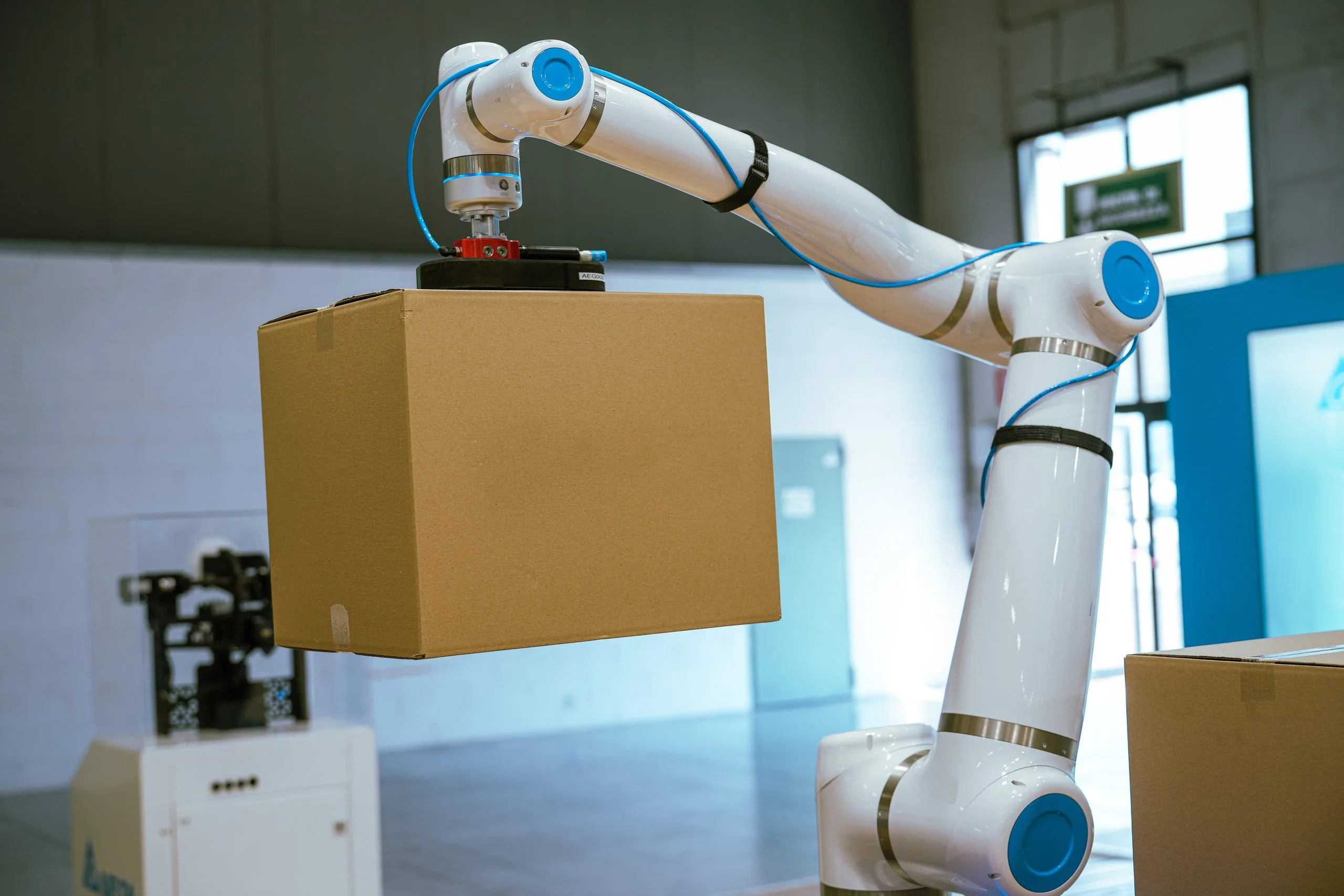
In robotic automation, the end effector, or End of Arm Tooling (EOAT), is where the digital instructions of the controller meet the physical realities of the workpiece. These terms refer to the specialized hardware mounted to a robot flange that interacts with parts, tools, or the surrounding cell environment.
The terms are interchangeable in practice in that end effector and EOAT both refer to whatever is attached to the robot flange to interact with the workpiece, whether that is a gripper, a vacuum tool, or a multi-function combination head.
While industrial robotic arms and cobots are standardized, mass-produced assets, custom end effectors are typically engineered around part geometry, surface properties, and cycle time demands. Because EOAT directly contacts the product, it is subjected to continuous wear, high dynamic loads, and friction, and it must handle parts securely without damaging them.
Whether you’re scaling a pick-and-place cell or developing hardware for next-generation robotic systems, custom end effector design requires a focus on manufacturing feasibility, mechanical durability, and replaceability. This guide covers EOAT architecture, material selection, manufacturing considerations, and design strategies for robotics manufacturing processes.
Types of End Effectors and Custom Parts
Standard components such as gripper bodies, suction cups, vacuum generators, and tool changer master plates can be purchased off the shelf. The physical interfaces, including custom jaw profiles, vacuum manifolds, and mounting brackets, are typically engineered for the specific application. The table below summarizes the split, and the sections that follow cover the main end effector types and where custom design comes in.
| Subsystem | Standard (off-the-shelf) | Custom-engineered |
| Grippers | Pneumatic or electric gripper bodies | Contoured fingers and jaws, elastomer contact pads |
| Vacuum | Suction cups, vacuum generators | Vacuum frames, distribution manifolds, tubing layout |
| Magnetic and compliance | Permanent or electro-permanent magnet bodies, commercial compliance units | Pole pieces, contoured magnetic shoes, spring packs, flexures, RCC geometry |
| Tool changers | Robot-side and tool-side master plates | Adapter plates, pass-through brackets for pneumatic, electrical, and sensor lines |
| Sensors | Proximity switches, force/torque sensors, vision cameras | Mounts, recessed pockets, guard shrouds |
Grippers (Parallel Jaw, Three-Finger, Angular)
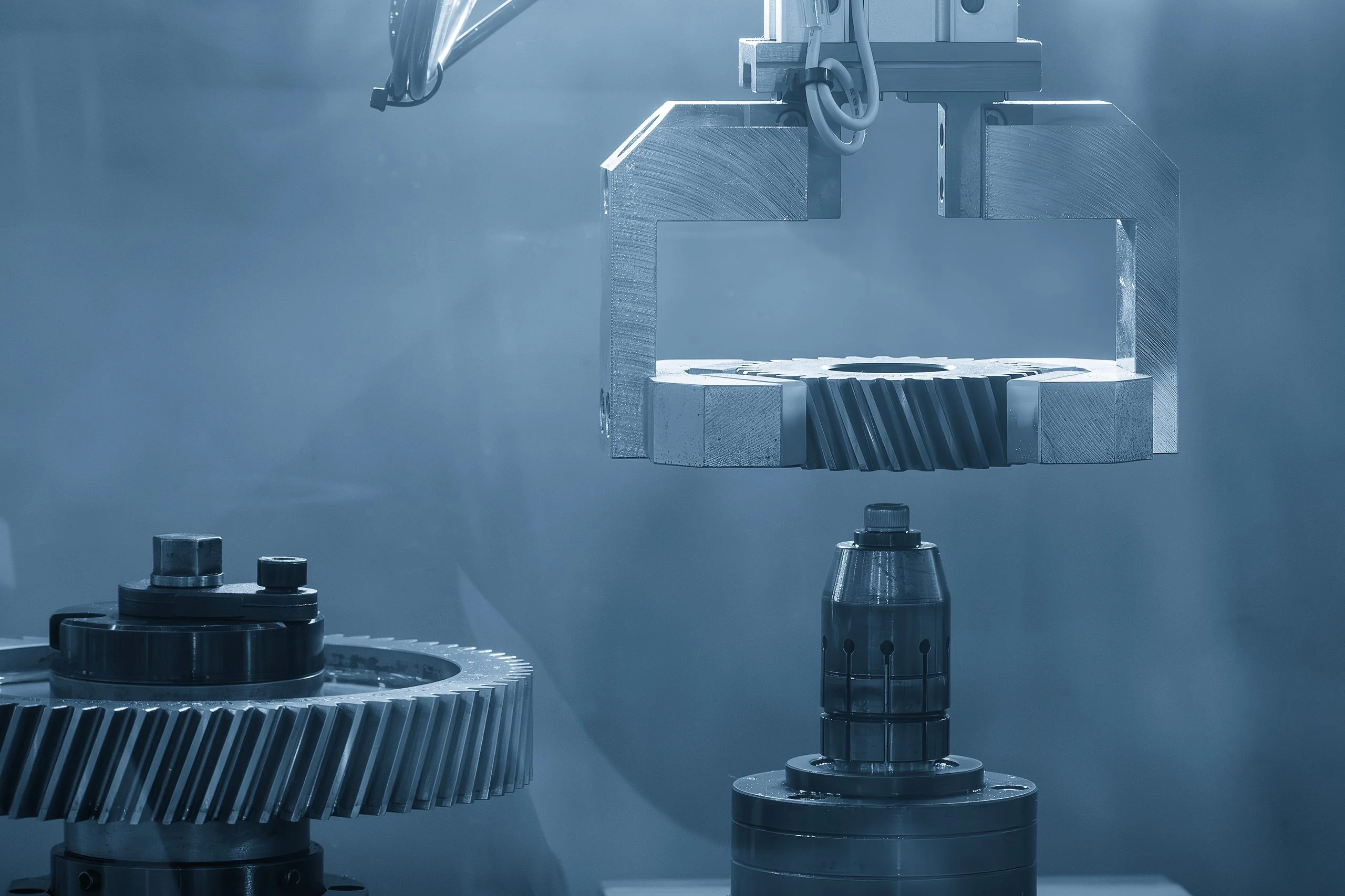
Off-the-shelf electric or pneumatic gripper bodies provide the internal actuation, but standard flat fingers can’t always hold real-world parts securely. Custom gripper fingers with contoured geometries, compliant pockets, or specific clearance angles are manufactured to match the workpiece’s CAD model. Custom fingers prevent part slippage during high-acceleration movement without requiring excessive clamping force that could damage delicate surfaces.
Common applications: Machine tending, part loading and unloading, part transfer, and assembly.
Vacuum Cup Assemblies
Vacuum end-of-arm tooling uses standard off-the-shelf suction cups and vacuum generators, but the underlying distribution manifold, mounting frame, and tubing architecture are frequently custom. Custom aluminum or 3D-printed vacuum frames position multiple cups precisely across irregular surface contours, ensuring balanced lifting points and preventing part deflection on thin sheet metal or molded components.
Common applications: Packaging, palletizing, sheet metal and panel handling, and pick-and-place on assembly lines.
Compliance Mechanisms
Passive and active compliance mechanisms allow a robot end effector to compensate for slight part misalignments during high-precision insertion or assembly tasks. Custom compliance end effectors utilize calibrated spring packs, flexures, or remote center compliance (RCC) geometry engineered specifically for the directional forces and mass properties of a target assembly.
Common applications: Peg-in-hole insertion, press-fit and connector assembly, and any task with slight part misalignment.
Magnetic Grippers
Rare-earth permanent magnets or electro-permanent magnetic grippers are commonly used to handle ferrous parts. Custom pole pieces and contoured magnetic shoes are machined to maximize surface contact area on non-flat metal stampings, castings, or mixed-material subassemblies.
Common applications: Loading and unloading steel stampings, castings, and sheet metal in press lines and machine cells.
Tool Changers
Automatic and manual tool changers use standardized robot-side and tool-side master plates. However, the adapter plates that interface the tool-side changer to the custom EOAT body, along with pass-through brackets for pneumatic, electrical, and sensor lines, are custom-designed to maintain stiffness and pass signals reliably through the interface.
Common applications: Cells where one robot switches between tools or part variants, such as a gripper and a vacuum tool.
Custom Combination Tooling
Complex automation cells often combine multiple functions into a single EOAT head, such as parallel gripper jaws, pneumatic vacuum cups, distance sensors, and vision camera mounts. Integrating these subsystems into one assembly requires a fully custom lightweight frame that balances mass distribution while avoiding collisions within the cell envelope.
Common applications: Multi-step cells, such as pick, inspect, and place with one head, that avoid tool changes between steps.
Have an EOAT design ready? Upload your CAD for a quote and DFM feedback
Materials for Custom End Effectors
Selecting the right material for robotic end effectors involves balancing yield strength, mass, stiffness, wear resistance, and total manufacturing costs. Below is a breakdown of the primary materials used across structural EOAT bodies, custom fingers, and wear components.
| Material | Primary Manufacturing Process | Best For | Key Limitations |
| 6061-T6 Aluminum | CNC Machining | Structural EOAT bodies, mounting plates, rigid fingers | Lower yield strength (than 7075) |
| 7075-T6 Aluminum | CNC Machining | High-load structural bodies, high-stress mounting links | Poor weldability |
| PA12 Nylon | 3D Printing (SLS/MJF) | Contoured fingers, vacuum manifolds, sensor brackets | Wear surface degrades faster; not suitable for high temps; need sealing for vacuum |
| Acetal/PEEK | CNC Machining | Machined fingers, locating pads, wear plates; PEEK for high-temperature or chemical resistance | Lower stiffness than metal; acetal has limited temperature range; PEEK is costly |
| TPE / TPU / Silicone | Compression or Injection Molding | Compliant finger inserts, soft grippers for delicate parts | Nonstructural |
| 316L Stainless Steel | CNC Machining | Food processing, washdown, and highly corrosive cells | Significant weight penalty; reduces available payload |
6061-T6 Aluminum
6061-T6 is the default structural material for EOAT construction. It offers an excellent strength-to-weight ratio, superior machinability, and low raw material cost. Anodizing the finished part increases wear resistance and allows color-coding for rapid visual tool identification on the factory floor, although a slight increase in thickness should be accounted for.
7075-T6 Aluminum
When dealing with heavy payloads or tight volumetric constraints where 6061-T6 yield strength is insufficient, 7075-T6 offers a higher-strength alternative (roughly 500 MPa yield strength) at a fraction of the weight. Because 7075-T6 has poor weldability, parts should be designed for pinned and bolted mechanical assemblies.
SLS/MJF Nylon (PA12)
PA12 nylon processed via Selective Laser Sintering (SLS) or Multi Jet Fusion (MJF) is widely used for custom gripper fingers, sensor shrouds, and vacuum distribution manifolds. Powder-bed fusion processes create near-isotropic parts with good tensile strength and high geometric freedom without requiring temporary support structures.
Machined Engineering Plastics (Acetal and PEEK)
Machined plastics are good options for fingers, locating pads, and wear plates where metal would mar the part or add mass. Acetal (POM) is stiff, low-friction, and dimensionally stable, making it a common default. PEEK is more expensive and should be reserved for demanding environments requiring thermal stability, chemical resistance, or repeated sterilization.
TPE/TPU and Silicone
Fragile workpieces such as glass vials, polished cosmetic housings, or delicate electronics require elastomeric contact interfaces. Soft polymers like TPE, TPU, or silicone pads are mechanically fastened or overmolded onto rigid metallic or printed finger backings. The durometer (shore hardness) should be matched to the required friction coefficient and part fragility.
316L Stainless Steel
In washdown, caustic, or food-grade processing cells, stainless steel is commonly specified to satisfy sanitary requirements and prevent oxidation. Due to its higher density compared to aluminum, stainless steel components should be pocketed out to minimize mass.
CNC Machining vs. 3D Printing for End Effectors
The decision to CNC machine or 3D print an end effector depends on target tolerances, mechanical loads, production volumes, and iteration speed.
While CNC machining delivers structural stiffness and precision mounting interfaces, 3D printing enables complex internal passages and rapid replacement of wear parts.
When to CNC Machine
CNC machining is necessary for high-load structural frames, base plates, and direct robot flange interfaces. Features requiring precise alignment, such as dowel pin registration holes, linear guide rails, or bearing seats, require the dimensional control of precision milling.
- Tolerances: Holds features to ±0.05 mm or tighter.
- Stiffness: High Young’s modulus prevents frame flexing during high-acceleration moves.
- Durability: Resists thread stripping under repeated high-torque dynamic cycles.
When to 3D Print (SLS/MJF)
Powder-bed fusion 3D printing techniques like SLS and MJF are ideal for complex contact geometries, internal fluid/vacuum routing channels, and secondary bracketry.
- Geometric Freedom: Organic contact surfaces that match complex workpiece profiles without multi-axis indexing setup costs.
- Mass Reduction: Internal lattice structures remove dead weight from nonstructural sections.
- Speed: Rapid iteration from CAD model to physical functional testing in under 48 hours.
The Hybrid Approach
The most reliable production EOAT architectures use a hybrid approach: a CNC-machined aluminum structural core paired with 3D-printed PA12 wear components and custom fingers. This ensures the robot flange interface remains stiff, repeatable, and securely mounted, while the application-specific wear components can be produced cost-effectively and replaced quickly when worn.
Note: many EOAT components are machined or 3D-printed because automation setups are inherently low-volume and highly customized, though extremely high-volume, standardized automation programs may occasionally justify casting or injection molding to lower per-part costs.
Critical Dimensions and Tolerances for EOAT
Inaccurate tolerances on an end effector shift the robot’s Tool Center Point (TCP) from its programmed offset, and loose fits or flex reduce repeatability. Poorly held dimensions can also increase mechanical stress on internal arm gearboxes and cause unexpected cell faults.
Robot Flange Interface (ISO 9409-1 Standards)
The custom mounting plate that bolts to the robot flange must match the robot’s ISO 9409-1 flange pattern, which defines the bolt circle, locating features, and interface dimensions. The standard doesn’t set tolerances for the plate itself, so use the following as recommended design targets and confirm them against the robot manufacturer’s flange drawing:
- Flatness: Hold the mounting face flat within ≤0.05 mm to avoid warping the robot flange or inducing bending moments into the tool changer mechanism.
- Dowel Pin Alignment: Use precision engineering fits on dowel pin holes, such as an H7 hole with an h6 or m6 dowel (ISO 286), to ensure exact repositioning each time the tool is removed and reattached.
Gripper Jaw Parallelism
For parallel jaw grippers, keep the finger mounting surfaces parallel across the full stroke length, ideally within 0.1–0.2 mm. Lack of parallelism causes uneven contact pressure, leading to part twist or premature wear on the actuator’s linear guide rails.
Finger Tip Geometry
Critical contact points that define the TCP must be held to tight tolerances. If finger pads are produced via 3D printing, machine or post-process primary locating datums to ensure accurate, repeatable part picking.
Mass and Center of Gravity
Calculating payload capacity requires factoring in the combined mass of the custom EOAT and the workpiece, evaluated at the tool’s true center of gravity at maximum extension. Overlooking offset distances can overload axis gearboxes even if total static weight is within nominal robot limits.
Cable and Pneumatics Management
Improperly routed pneumatic tubing and signal cables are a common cause of downtime during cell commissioning. Design explicit strain relief points, integrated cable guide channels, or slip-ring mounts directly into the custom EOAT body. Ensure bend radii for all lines account for manufacturer limits across the full rotation of the wrist joints.
Designing EOAT for Durability and Replaceability
High-volume automation requires tooling designed for maintenance and serviceability.
Design for Consumable Wear Cycles
Treat gripper fingers, suction cups, and elastomeric pads as wear components. Isolate them from structural frames using modular, pinned mountings so technicians can swap them out quickly without removing the main assembly from the robot.
Standardize Hardware
Use consistent fastener socket sizes where possible so maintenance teams can service the tooling using a single tool.
Hardware Marking and Revision Tracking
Laser engrave or machine part numbers, CAD revision indices, and default TCP offset coordinates directly onto the aluminum EOAT housing. This ensures technicians can re-verify offsets accurately after swapping components.
Sensor Protection and Collision Guards
Inductive proximity switches, force/torque sensors, and vision camera lenses are vulnerable to cell collisions. Recess sensors inside machined pockets, install physical guard shrouds, or add mechanical shear-pin breakaway mounts and collision sensors to protect expensive optics and electronics during unexpected crashes.
Scale Your Custom EOAT Programs with Fictiv
Navigating custom tooling development requires fast turnarounds and dependable manufacturing quality. Whether you need CNC-machined structural base plates, complex 3D-printed gripper fingers, or custom sheet metal brackets, Fictiv delivers high-precision custom hardware to keep your automation cells running.
Upload your CAD models to the Fictiv platform today for instant DFM analysis, real-time pricing, and fast lead times on custom robotic components.
Talk to a Fictiv expert about your project, or upload your parts to start a free quote.
FAQs About Custom End Effectors
What is End of Arm Tooling (EOAT)?
End of arm tooling (EOAT), also called an end effector, is the hardware mounted to a robot flange that interacts with parts, tools, or the surrounding cell. Robot arms are standardized, but EOAT is usually custom-engineered around part geometry, surface properties, and cycle time. Common types include grippers, vacuum cup assemblies, compliance devices, magnetic grippers, tool changers, and combination tooling.
Is 3D-printed PA12 durable enough for production gripper fingers?
Yes, if you treat it as a replaceable wear component. PA12 printed via SLS or MJF has good tensile strength and suits contoured fingers, sensor shrouds, and vacuum manifolds. Its wear surface degrades faster than metal, and it is not suited to high temperatures. Vacuum manifolds also need sealing. Pair printed fingers with a CNC-machined aluminum core.
When should I CNC machine an end effector instead of 3D printing it?
CNC machine high-load structural frames, base plates, and robot flange interfaces. Also machine features that need precise alignment, such as dowel pin holes, guide rails, and bearing seats. Machining gives tighter tolerances, higher stiffness, and better thread durability. 3D print complex contact geometries, internal vacuum channels, and secondary brackets. Most reliable production designs combine both in a hybrid architecture.
How do I choose a material for a custom end effector?
Balance yield strength, mass, stiffness, wear resistance, and total manufacturing cost:
- 6061-T6 aluminum is the default for structural bodies.
- 7075-T6 suits heavy payloads or tight volumetric constraints.
- PA12 nylon works for printed fingers and manifolds.
- Acetal or PEEK suits machined fingers and wear plates, with PEEK for high temperature or chemical exposure.
- TPE or silicone pads protect fragile parts.
- 316L stainless steel fits washdown cells but adds weight and reduces available payload.
Which parts of an end effector are custom, and which are off-the-shelf?
Gripper bodies, suction cups, vacuum generators, and tool changer master plates are typically standard. The physical interfaces are custom: gripper fingers, vacuum manifolds and frames, magnetic pole pieces, compliance geometry, tool changer adapter plates, and mounting brackets. These are engineered to the workpiece’s geometry, surface properties, and cycle time demands.