Time to read: 8 min
Warping is a common defect in injection molding that creates distortion of a plastic part after ejection. Warpage is caused by uneven shrinkage, as a result of residual stresses or cooling imbalances, and often appears as twisting, bending, or dimensional inaccuracy.
Root causes include nonuniform wall thickness, improper mold design, material shrinkage rates, and inadequate processing parameters. Warpage can be minimized through effective part design, optimized cooling, material selection, and process adjustments, such as holding pressure and mold temperature balance.
In CAD, it’s fairly easy to make a straight, flat surface. But in injection molding, you are dealing with much more complexity than a couple clicks of a mouse. Various design and processing factors can lead to warping and other associated defects.
What Warpage Means To Product Development Teams
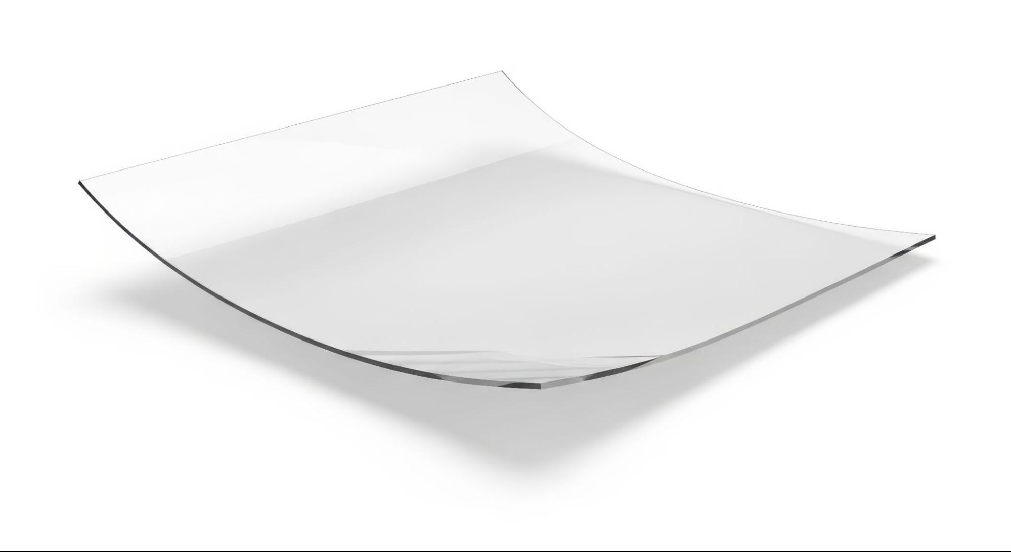
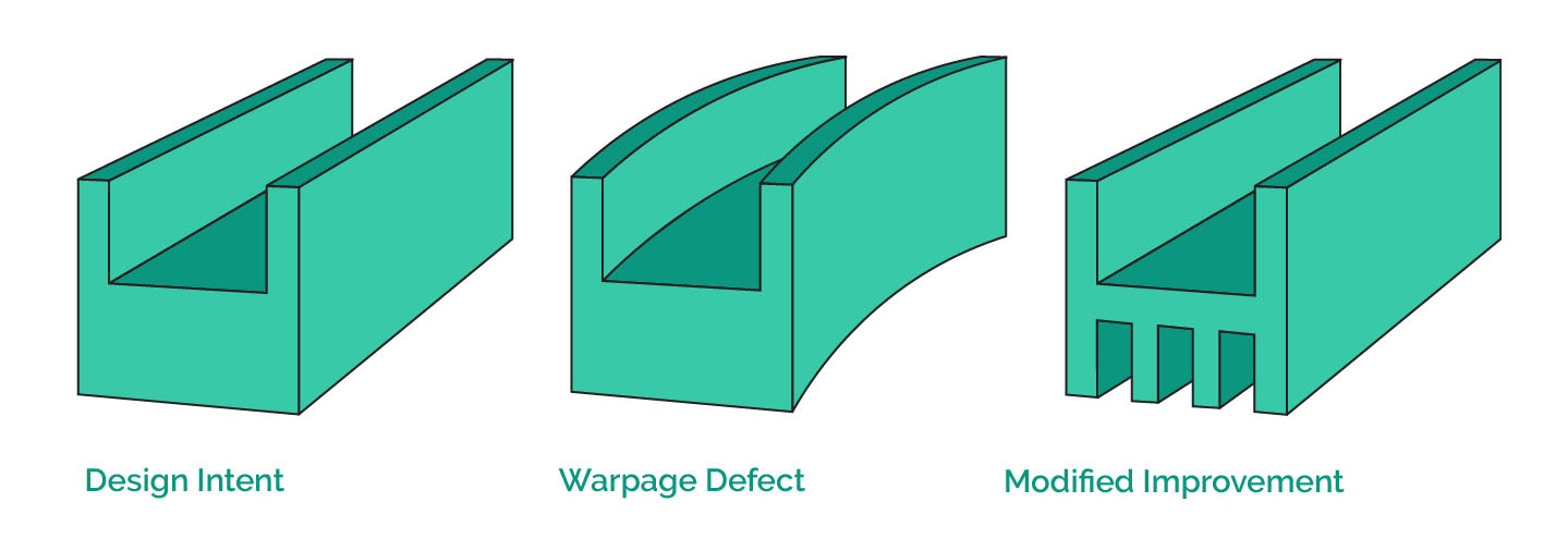
Warp occurs when a molded part deviates from its intended shape after ejection and cooling, usually due to twisting, bending, or bowing out of tolerance. While the part may appear dimensionally accurate inside the mold, it can distort as internal stresses arise during cooling or after ejection.
For manufacturers, warpage means rework, rejects, and added cost. For designers, it means compromised functionality, i.e., assemblies don’t fit, surfaces misalign, and cosmetic quality suffers. Understanding why plastic parts warp and how to control them is critical to achieving consistent, dimensionally stable production.
Why Warpage Happens in Plastic Parts
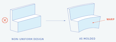
Fundamentally, warpage is caused by nonuniform shrinkage. When molten plastic cools, it contracts. If different areas of a part shrink by different amounts or in different directions, residual stresses are introduced. The effects of these stresses become visible as the part warps once it’s free from mold constraints. The various causes of warpage are explained in more detail below.
Differential Shrinkage
All molten plastics shrink as they solidify, but usually not uniformly. Factors such as wall thickness, cooling rate, and material type influence the extent to which a region shrinks. For example, thicker sections cool more slowly and therefore are susceptible to uneven shrinkage within the wall itself. Semi-crystalline materials can shrink between 1–3%, while amorphous materials typically shrink less than 0.7%.
Add to this the fact that the ideal pressure to successfully mold a thick wall is often different (generally less) than for a thin wall in the same part, and the significant benefit of maintaining uniform wall thicknesses becomes apparent. Additionally, the fibers in fiber-reinforced polymers restrict shrinkage along their orientation, creating directional (anisotropic) contraction that can bend or twist a part.
Residual Stresses
Residual stresses form in a part due to temperature gradients (where parts are cooler at the surface but hotter at the interior) and flow-induced molecular orientation during molding. When the polymer molecules are stretched and solidified during melting and cooling, molecules are rearranged, and internal tensions are introduced. Upon mold ejection, these stresses are relieved unevenly, causing the part to bend or twist. Some residual stress can relax over time or under heat, which can cause delayed warpage.
Cooling Imbalances
Parts rarely cool uniformly. Uneven mold temperatures, poorly balanced cooling channels, or inconsistent cycle times can cause one side of the part to cool and solidify faster than the other. This results in differential shrinkage across the part, which often leads to warpage.
Common Causes of Warping in Plastic Injection Molding
Warpage often occurs due to a variety of factors, including part design, material behavior, molding conditions, and mold construction. Understanding these interdependent factors is the key to solving warping. Explained below are some of the different causes of warping.
Part Design
- Wall Thickness Variation: The most common design-related cause of warpage. Thick and thin sections cool at different rates, creating shrinkage gradients.
- Uneven Geometry: Asymmetric shapes, large flat surfaces, or cantilevered features can act as stress concentrators or cool unevenly.
- Lack of Structural Support: Large, flat parts without ribs or gussets tend to warp easily since there’s little geometry to resist internal stress.
Material Properties
- High Shrinkage Polymers: Semi-crystalline materials, such as PP, POM, and PA6, exhibit higher and more anisotropic shrinkage than amorphous materials, like ABS or PC.
- Fiber Orientation Effects: In glass-filled materials, the alignment of fibers during flow restricts shrinkage along the fiber direction. If the flow is unbalanced, warpage is amplified.
- Moisture Sensitivity: Some polymers absorb moisture after molding, which leads to post-mold dimensional changes that mimic warpage.
Processing Parameters
- Melt and Mold Temperature: Higher melt temperatures can increase shrinkage due to the higher temperature gradients present in the part. However, this is not universally the case—for example, a complex or intricate mold design may necessitate high melt and mold temperatures to improve polymer flow through narrow sections. Either way, the added presence of uneven mold temperature distribution leads to uneven cooling.
- Packing and Holding Pressure: Insufficient or uneven packing pressure allows uneven shrinkage between thick and thin regions.
- Cooling Time: Inadequate cooling before ejection can cause the part to warp as it continues to solidify outside of the mold. This is due to the differences in the mold temperature and ambient temperature.
Mold Design
- Cooling Channel Layout: Poorly distributed or unbalanced cooling lines lead to temperature gradients that directly cause warpage.
- Gate Location and Type: The position and size of gates determine flow paths and packing efficiency. Asymmetric gating can create uneven shrinkage, causing plastic molecules to deviate from optimal orientation.
- Mold Venting: Inadequate venting may trap air, affecting pressure distribution and contributing to inconsistent packing.

How to Reduce Warping in the Injection Molding Process
Warpage can be mitigated through thoughtful design, precise process control, material selection, and optimized mold construction. Listed below are some of the solutions to reduce warping in plastic injection parts.
Part Design Improvements
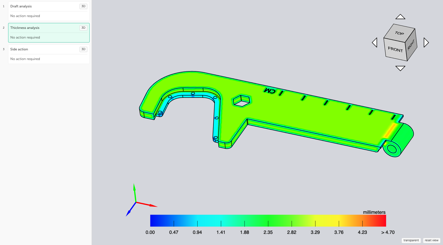
- Uniform Wall Thickness: Keep wall sections as consistent as possible. If variations are unavoidable, transition walls gradually, using fillets or tapers.
- Avoid long, thin, unsupported sections: These can be prone to warping as the part will cool faster with the higher surface area-to-volume ratio.
- Use Ribs Instead of Thick Walls: Ribs provide stiffness and strength without creating thick sections that cool unevenly.
- Add Draft and Radii: Proper draft angles and corner radii reduce stress concentrations and promote uniform ejection forces.
- Symmetry: Symmetrical designs shrink more evenly. When asymmetry is necessary, design countermeasures such as balanced ribbing or thicker opposite walls.
See our injection molding design guide for additional DFM best practices.
Process Optimization
- Adjust Holding Pressure and Time: Increase packing pressure or extend mold holding time to minimize differential shrinkage, particularly in thicker zones.
- Optimize Cooling Time: Ensure parts cool sufficiently below the glass transition temperature before ejection.
- Balance Mold Temperature: Maintain consistent temperature across the mold using proper cooling design and process monitoring. Keep mold half temperature differentials within ±2 °C to prevent directional warp.
- Mold Opening and Ejection: Reduce ejection stresses by using uniform ejection force, sufficient ejector pins in difficult-to-release areas, and delayed mold opening if necessary.
Material Strategies
- Choose Low-Shrinkage Polymers: Amorphous polymers (like PC, PMMA, ABS) generally exhibit more predictable, isotropic shrinkage than semi-crystalline polymers.
- Fiber Orientation Control: Modify gate placement or flow paths to align fibers in a way that balances shrinkage.
- Add Fillers or Blends: Minerals, glass, or other fillers can reduce shrinkage and improve stiffness, but must be used carefully to avoid uneven orientation.
- Annealing: Can relieve residual stress in semi-crystalline materials like PA or PBT.
Mold Design Enhancements
- Balanced Cooling System: Design cooling channels with consistent spacing and distance from the cavity surface to balance cooling.
- Multiple Gates: Use multiple or symmetrically placed gates to balance flow and reduce differential shrinkage.
- Moldflow Simulation and Flow Balance: Use simulation software such as Moldflow to virtually test and optimize cooling and gating strategies before cutting steel to predict warpage risks early. Flow leaders or restrictors can help balance flow paths in asymmetrical cavities.
- Use Conformal Cooling: In complex molds, conformal cooling channels (via additive manufacturing) can drastically improve temperature uniformity. Such channels conform to the shape of the part and are generally effective.
How to Troubleshoot Warpage in Injection Molding
Below is a diagnostic table summarizing common injection molding warpage symptoms, their likely causes, and corrective actions:
| Symptom | Likely Cause | Corrective Action |
| Part bends toward thicker section | Uneven cooling through thicker walls introduces stresses | Balance wall thickness; improve cooling near thick areas |
| Corners lift or twist | Asymmetric geometry or fiber orientation | Modify gate location; adjust rib placement; control flow direction |
| Part bows in one direction | Temperature gradient across part | Improve cooling uniformity; balance mold temperature |
| Sink marks and local warpage | Low packing pressure | Increase holding pressure/time; adjust gate size |
| Warpage increases over time | Residual stress effect or moisture absorption | Consider the use of post-mold annealing time; dry parts before use |
| Warpage only in glass-filled version | Uneven fiber orientation | Adjust gate location or flow path; reduce injection speed |
Table 1: Common Warpage Symptoms, Causes, and Corrective Actions
Tools for Predicting and Analyzing Warpage
Modern design and simulation tools allow engineers to predict and correct warpage before molds are even built. Below are some tools to predict and analyze warpage.
Simulation Software
Moldflow, Moldex3D, Sigmasoft, and other software can simulate the filling, packing, and cooling phases of injection molding. These programs predict shrinkage, temperature gradients, and fiber orientation fields to give engineers insight into potential warpage behavior.
A typical workflow includes:
- Importing CAD geometry and material data.
- Simulating the mold filling and cooling process.
- Evaluating predicted warpage contours and deformation vectors.
- Iteratively modifying gate locations, cooling channels, or wall thicknesses to reduce deformation.
DFM Feedback Loops
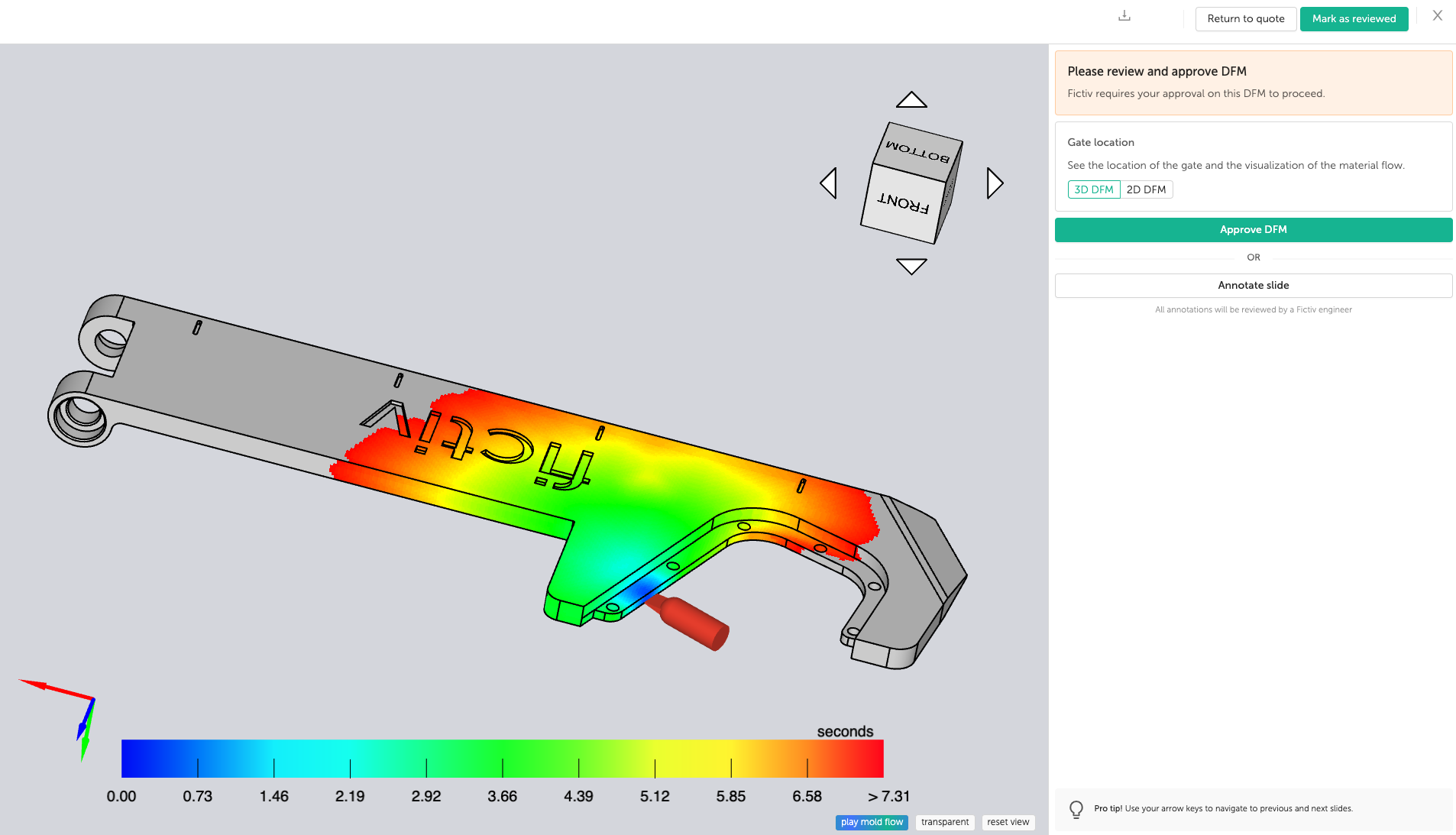
Beyond simulation, Design for Manufacturability (DFM) evaluations can involve molders and design engineers early in the design process. This collaboration ensures that design intent, material choice, and process settings are optimized together, not in isolation. DFM feedback loops shorten the product development cycle and prevent costly retooling later.
Experimental Validation
Even with sophisticated modeling, real-world validation is essential. Using test molds or 3D-printed inserts allows engineers to experimentally verify cooling and warpage tendencies before full production. Simulation data should be correlated with real molded part CMM measurements to validate predicted warpage vectors and scaling factors.
Real-World Examples and Applications of Warping
Example 1: Flat Electronic Housing
A consumer electronics company experiences persistent warpage on a large ABS housing panel. Simulation shows uneven cooling due to a lack of channels beneath mounting bosses. By redesigning the mold with additional cooling near those features and slightly increasing the packing pressure, warpage is reduced by over 70%, bringing the assembly back within tolerance.
Example 2: Glass-Filled Nylon Bracket
An automotive bracket molded in 30% glass-filled nylon warps consistently in one direction. Moldflow analysis reveals that fiber orientation is heavily biased along one axis due to the gate location. Relocating the gate to the center of mass balances the fiber alignment and reduces warpage without changing material or process parameters.
Example 3: Warpage Reduction via Conformal Cooling
In a high-precision optical component, conventional straight cooling channels produce temperature gradients exceeding 10°C across the cavity surface. By switching to conformal cooling channels made with metal 3D printing, temperature variation drops below 2°C, and post-mold warpage is effectively eliminated.
Designing for Warp Resistance
Warpage is a controllable variable when engineers design with it in mind. The root cause is always some form of uneven shrinkage, whether driven by material properties, cooling imbalance, or part geometry.
The best strategy is prevention through collaboration and simulation:
- Design parts with uniform wall thickness and balanced geometry.
- Use simulation tools to evaluate flow, cooling, and shrinkage early.
- Partner with molders who can tune process parameters precisely and apply DFM insights.
In short, designing for warp resistance means thinking holistically—integrating material science, tooling design, and process engineering into a single, feedback-driven workflow.
Are you struggling with part warpage or other defects? Fictiv provides expert DFM feedback, moldflow simulation insights, and precision injection molding services to help you produce dimensionally stable parts faster. Whether you’re developing high-tolerance enclosures, structural brackets, or optical components, our engineers help you design, predict, and eliminate warpage before it becomes a production headache.
Get a free quote on injection molding today.


